EasyManua.ls Logo

Omron SYSMAC CV Series User Manual

Omron SYSMAC CV Series
636 pages
To Next Page IconTo Next Page
To Previous Page IconTo Previous Page
Page #434 background imageLoading...
Page #434 background image
422
Do not change the control data during a transmission (i.e., while the correspond-
ing Port Enabled Flag in A502 is OFF).
The Execute Error Flag for the designated port will be turned ON if no response
is received in the response monitoring time (C+5), the amount of command data
transmitted exceeds the maximum for the system, or the response data exceeds
the number of bytes specified in C+1.
The amount of response data can be less than the “number of bytes to receive”
in C+1 without causing an error, but the amount of the command data must
agree with the “number of bytes to send” in C or a command length error will oc-
cur. Be sure that the command data and response data do not go over the end of
a data area.
CMND(194) only starts the transmission of command data. Verify that the trans-
mission has been completed with the Network Status Flags in A502. If data is
changed before transmission is completed, the data might be transmitted while
data is being changed.
Note Refer to page 115 for general precautions on operand data areas.
Flags ER (A50003): Content of *DM word is not BCD when set for BCD.
Example This example shows CMND(194) used to transmit a command to the PC on
node 3 of network 1 to change the PC to MONITOR mode when CIO 00000 is
ON. D05001 is the first word to receive the response, and D04001 through
D04003 contain the command data.
00000 LD 000000
00001 CMND(194)
D04001
D05001
D01001
Address Instruction Operands
0000
00
(194)
CMND D04001 D05001 D01001
Word Content
D04001 0401
D04002 0000
D04003 0002
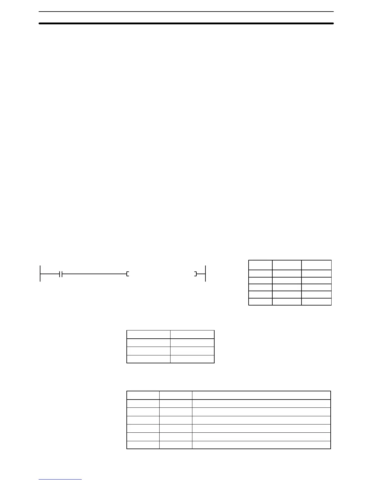
D01001 to D01006 contain the control data, as shown below.
Word Content Function
D01001 0006 Number of bytes to send = 6
D01002 0100 Number of bytes to receive = 256
D01003 0001 Destination network address = 01
D01004 0300 Destination node number = 03; unit = PC
D01005 0207 Response returned; transmission port = 2; retries = 7
D01006 0064 Response monitoring time = 10 seconds
Network Instructions Section 5-36

Table of Contents

Question and Answer IconNeed help?

Do you have a question about the Omron SYSMAC CV Series and is the answer not in the manual?

Omron SYSMAC CV Series Specifications

General IconGeneral
SeriesSYSMAC CV Series
TypePLC
Input Voltage100 to 240 VAC, 24 VDC
Number of InputsVaries by model
Number of OutputsVaries by model
I/O CapacityUp to 2048 points
I/O PointsVaries by model
Communication PortsRS-232C, RS-422/485
Programming LanguageLadder Logic
Power Supply100-240V AC or 24V DC
MountingDIN rail mounting
Operating Temperature0°C to 55°C

Summary

PRECAUTIONS

2 General Precautions

User must operate product per specifications; consult OMRON for non-manual conditions or critical systems.

3 Safety Precautions

Precautions regarding power supply, terminal touching, disassembly, repair, and battery handling.

4 Operating Environment Precautions

Guidelines for environmental conditions for PC system installation and operation.

5 Application Precautions

Precautions for safe PC system usage, grounding, power supply, wiring, and program changes.

SECTION 1 Introduction

SECTION 2 Hardware Considerations

2-3 Memory Cards

Covers file memory used to store programs and other data, including RAM, EPROM, and EEPROM types.

2-7 PC Configuration

Provides an overview of the PC configuration, including CPU Rack, Expansion CPU Rack, and Expansion I/O Rack.

SECTION 3 Memory Areas

3-2 Data Area Structure

Describes two sets of addresses for accessing PC memory: data area addresses and memory addresses.

3-3 CIO (Core I/O) Area

Details CIO Area addresses, divided into eight data areas for I/O control and internal data manipulation.

3-6 Auxiliary Area

Contains flags and control bits for monitoring and controlling PC operation, accessing clock pulses, and signaling errors.

SECTION 4 Writing Programs

4-1 Basic Procedure

Outlines basic steps for writing a program, including I/O device list and work bit allocation.

4-3 Basic Ladder Diagrams

Describes ladder diagrams, which consist of vertical lines (bus bars) and branching lines (instruction lines or rungs).

4-7 Controlling Bit Status

Lists instructions used to control individual bit status, such as OUTPUT, SET, RESET, and KEEP.

4-10 Programming Precautions

Provides guidelines on programming practices, such as unlimited conditions in series or parallel and avoiding vertical conditions.

SECTION 5 Instruction Set

5-6 Ladder Diagram Instructions

Covers instructions that correspond to ladder diagram conditions and logic block instructions for complex relationships.

5-7 Bit Control Instructions

Explains instructions used to control bit status by turning bits ON and OFF in different ways.

5-13 Timer and Counter Instructions

Details instructions for creating timers and counters, accessing PVs and Completion Flags.

5-15 Data Movement Instructions

Explains instructions used for moving data between different addresses in data areas.

5-16 Comparison Instructions

Covers instructions used for comparing data, affecting comparison flags and outputting results.

5-17 Conversion Instructions

Explains instructions that convert word data from one format to another, outputting converted data to specified result words.

SECTION 6 Program Execution Timing

6-2 Cycle Time

Explains operations affecting cycle time and I/O response time, and shows basic cycle time calculation.

6-5 I/O Response Time

Explains the time taken for the PC to output a control signal after receiving an input signal.

SECTION 7 PC Setup

SECTION 8 Error Processing

8-4 Error Messages

Classifies errors into initialization, non-fatal operating, and fatal operating errors for message display.

Appendices

A Instruction Set

Details all ladder diagram programming instructions, variations, and applicable data areas.

B Error and Arithmetic Flag Operation

Explains instructions affecting ER, CY, GR, LE, EQ, OF, UF, and N flags.

C PC Setup Default Settings

Lists default values for PC Setup parameters.

D Data Areas

Summarizes data areas in CV-series PCs, including CIO, Temporary Relay, and Auxiliary Areas.

Related product manuals