EasyManua.ls Logo

Omron SYSMAC CV Series User Manual

Omron SYSMAC CV Series
636 pages
To Next Page IconTo Next Page
To Previous Page IconTo Previous Page
Page #54 background imageLoading...
Page #54 background image
42
used in only one instruction that controls its status, including OUT, KEEP(11),
DIFU(13), DIFD(14), and SFT(10). If an output bit is used in more than one
such instruction, only the status determined by the last instruction will actual-
ly be output from the PC during the normal I/O refresh period.
If you control the status of an output bit in more than one instruction, be sure
to consider proper output timing and test the program before actual applica-
tion. See
5-14-1 SHIFT REGISTER – SFT(050)
for an example that uses an
output bit in two “bit-control” instructions.
I/O words in the CIO Area are allocated to Units mounted on Racks or other-
wise connected to the PC by performing the I/O Table Registration operation.
This operation creates in memory a table called an I/O table that records
what words and how many words are allocated to the Units and whether
these words are input or output words. The actual procedure for this opera-
tion is described in the
CVSS/SSS Operation Manuals
.
The first word allocated to each Rack can be set with the CVSS/SSS under the
PC Setup. When the I/O Table Registration operation is performed, the system
assigns word addresses to Units in the order in which they are mounted left to
right on each Rack, beginning with the first word set in the PC Setup. The as-
signed words must be between CIO 0000 and CIO 0511.
For any Racks not assigned a first word in the PC Setup menu when the I/O
Table is registered, the system automatically assigns word addresses to
Units. Word allocation begins with the leftmost Unit on the CPU Rack, and
then continues left to right on the CPU Expansion Rack or Expansion I/O
Rack with the lowest rack number set on its I/O Interface Unit. The order in
which the Expansion I/O Racks are connected is not relevant in word alloca-
tion, only the rack numbers. I/O words start from CIO 0000 for the first Unit
on the CPU Rack and continue consecutively: CIO 0001, CIO 0002, etc.
If the lowest word assigned to a Rack in the PC Setup menu is not higher than the
total number of words required by Racks that aren’t assigned a first word, the
same word will be assigned to two Units and a duplication error will occur. A du-
plication error will also occur if words assigned to Racks overlap those assigned
to Units controlled through Remote I/O Masters in the SYSMAC BUS/2 Area,
which begins at CIO 0200. Be careful when setting areas from the CVSS/SSS to
avoid overlapping allocations.
There are no specific words associated with any particular slot because dif-
ferent Units can require a different number of words. Rather, each Unit is as-
signed the next word(s) following the word(s) assigned to the previous Unit. If
there are any empty slots, no words will be assigned to those slots. Words
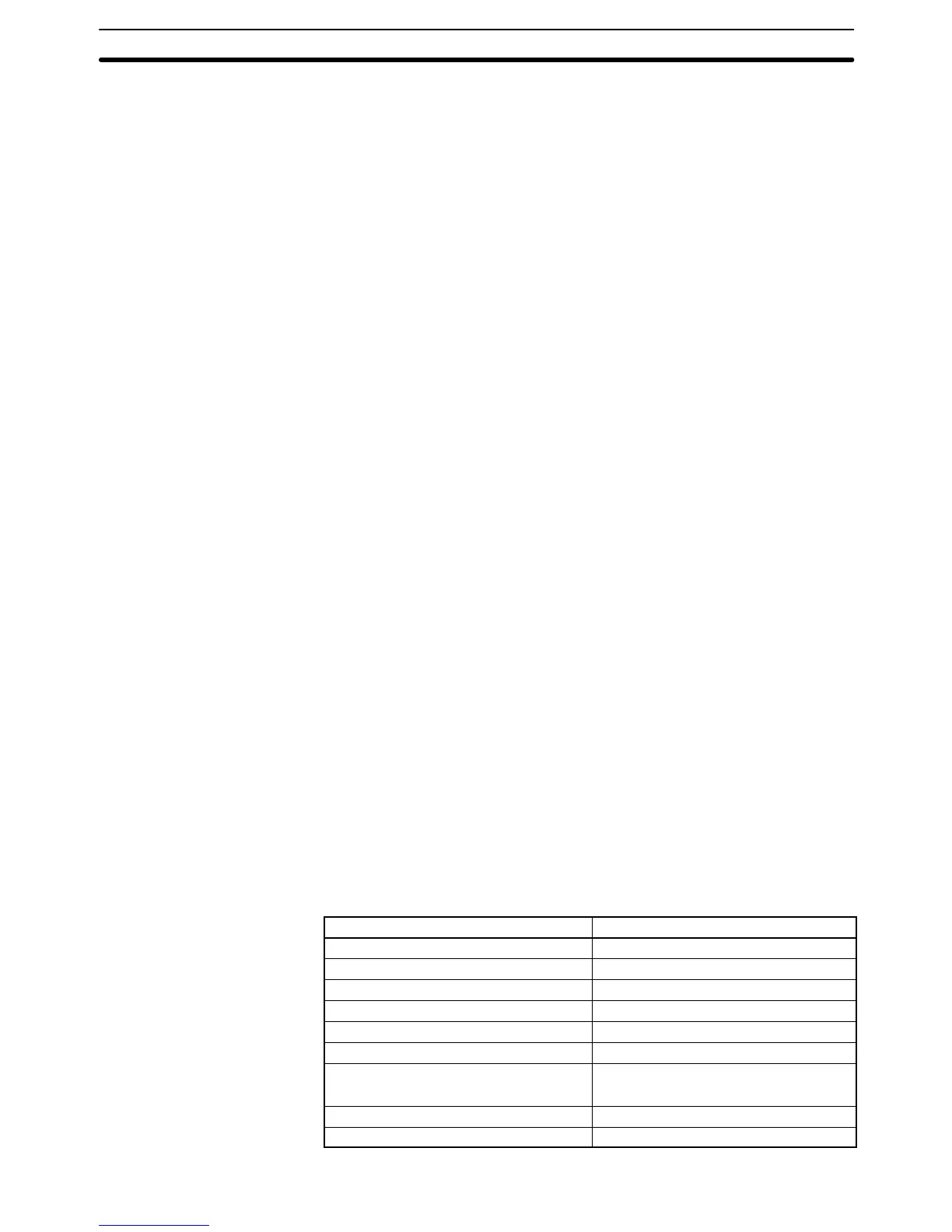
are only assigned when a Unit is mounted; all empty slots are skipped. The
numbers of I/O words allocated to the most common types of Unit are shown
below.
Unit Words required
16-pt I/O Units 1 word
24- or 32-pt I/O Units 2 words
64-pt I/O Units 4 words
Interrupt Input Unit 1 word
Dummy I/O Unit Set to 1, 2, or 4 words
Analog I/O Units 2 or 4 words
High-speed Counter Units CT012/CT041: 2 words
CT021: 2 or 4 words
MCR Units (See note 1) 4 words
PID Unit (See notes 1 and 2) 4 words
Word Allocations
CIO (Core I/O) Area Section 3-3

Table of Contents

Question and Answer IconNeed help?

Do you have a question about the Omron SYSMAC CV Series and is the answer not in the manual?

Omron SYSMAC CV Series Specifications

General IconGeneral
SeriesSYSMAC CV Series
TypePLC
Input Voltage100 to 240 VAC, 24 VDC
Number of InputsVaries by model
Number of OutputsVaries by model
I/O CapacityUp to 2048 points
I/O PointsVaries by model
Communication PortsRS-232C, RS-422/485
Programming LanguageLadder Logic
Power Supply100-240V AC or 24V DC
MountingDIN rail mounting
Operating Temperature0°C to 55°C

Summary

PRECAUTIONS

2 General Precautions

User must operate product per specifications; consult OMRON for non-manual conditions or critical systems.

3 Safety Precautions

Precautions regarding power supply, terminal touching, disassembly, repair, and battery handling.

4 Operating Environment Precautions

Guidelines for environmental conditions for PC system installation and operation.

5 Application Precautions

Precautions for safe PC system usage, grounding, power supply, wiring, and program changes.

SECTION 1 Introduction

SECTION 2 Hardware Considerations

2-3 Memory Cards

Covers file memory used to store programs and other data, including RAM, EPROM, and EEPROM types.

2-7 PC Configuration

Provides an overview of the PC configuration, including CPU Rack, Expansion CPU Rack, and Expansion I/O Rack.

SECTION 3 Memory Areas

3-2 Data Area Structure

Describes two sets of addresses for accessing PC memory: data area addresses and memory addresses.

3-3 CIO (Core I/O) Area

Details CIO Area addresses, divided into eight data areas for I/O control and internal data manipulation.

3-6 Auxiliary Area

Contains flags and control bits for monitoring and controlling PC operation, accessing clock pulses, and signaling errors.

SECTION 4 Writing Programs

4-1 Basic Procedure

Outlines basic steps for writing a program, including I/O device list and work bit allocation.

4-3 Basic Ladder Diagrams

Describes ladder diagrams, which consist of vertical lines (bus bars) and branching lines (instruction lines or rungs).

4-7 Controlling Bit Status

Lists instructions used to control individual bit status, such as OUTPUT, SET, RESET, and KEEP.

4-10 Programming Precautions

Provides guidelines on programming practices, such as unlimited conditions in series or parallel and avoiding vertical conditions.

SECTION 5 Instruction Set

5-6 Ladder Diagram Instructions

Covers instructions that correspond to ladder diagram conditions and logic block instructions for complex relationships.

5-7 Bit Control Instructions

Explains instructions used to control bit status by turning bits ON and OFF in different ways.

5-13 Timer and Counter Instructions

Details instructions for creating timers and counters, accessing PVs and Completion Flags.

5-15 Data Movement Instructions

Explains instructions used for moving data between different addresses in data areas.

5-16 Comparison Instructions

Covers instructions used for comparing data, affecting comparison flags and outputting results.

5-17 Conversion Instructions

Explains instructions that convert word data from one format to another, outputting converted data to specified result words.

SECTION 6 Program Execution Timing

6-2 Cycle Time

Explains operations affecting cycle time and I/O response time, and shows basic cycle time calculation.

6-5 I/O Response Time

Explains the time taken for the PC to output a control signal after receiving an input signal.

SECTION 7 PC Setup

SECTION 8 Error Processing

8-4 Error Messages

Classifies errors into initialization, non-fatal operating, and fatal operating errors for message display.

Appendices

A Instruction Set

Details all ladder diagram programming instructions, variations, and applicable data areas.

B Error and Arithmetic Flag Operation

Explains instructions affecting ER, CY, GR, LE, EQ, OF, UF, and N flags.

C PC Setup Default Settings

Lists default values for PC Setup parameters.

D Data Areas

Summarizes data areas in CV-series PCs, including CIO, Temporary Relay, and Auxiliary Areas.

Related product manuals