Call Out Description
1 Connector A tab
2 Left slide-rail front slot
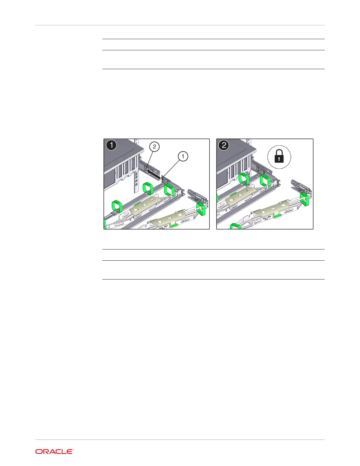
4. To install CMA connector B into the right slide-rail:
a. Insert CMA connector B into the front slot on the right slide-rail until it locks into place
with an audible click [1 and 2].
The connector B tab (callout 1) goes into the slide-rail front slot (callout 2).
b. Gently tug on the right side of the front slide bar to verify that connector B is properly
seated.
Call Out Description
1 Connector B tab
2 Right slide-rail front slot
5. To install CMA connector C into the right slide-rail:
a. Align connector C with the slide-rail so that the locking spring (callout 1) is positioned
inside (server side) of the right slide-rail [1].
Appendix C
Rackmounting the Server
C-19