11-32
FP2/FP2SH/FP10SH/FP3 (A: Available, N/A: Not available)
Name Descriptions
Read-
ing
Writ-
ing
FP3
FP2/
FP2SH
DT9022 DT90022
Scan time
(current value)
The current scan time is
stored here. Scan time is
calculated using the
formula:
Scan time (ms) = stored
data (decimal) x 0.1
Example:
K50 indicates 5 ms.
Scan time
display is
only possible
in RUN
mode, and
shows the
operation
cycle time.
The
maximum
and
minimum
values are
cleared
when each
the mode is
switched
between
RUN mode
and PROG.
mode.
A N/A
DT9023 DT90023
Scan time
(minimum
value)
The minimum scan time
is stored here. Scan time
is calculated using the
formula:
Scan time (ms) = stored
data (decimal) x 0.1
Example:
DT9024 DT90024
Scan time
(maximum
value)
The maximum scan time
is stored here. Scan time
is calculated using the
formula:
Scan time (ms) = stored
data (decimal) x 0.1
Example:
K125 indicates 12.5 ms.
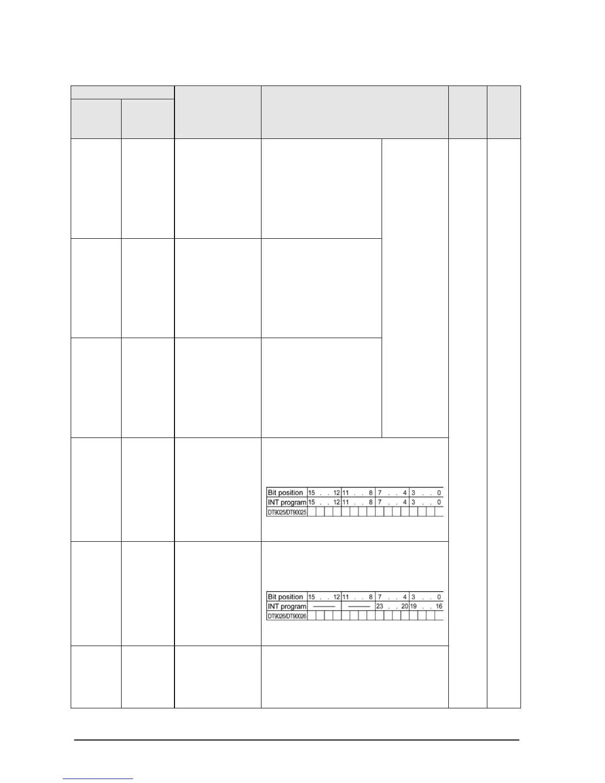
DT9025
(*Note)
DT90025
Mask condition
monitoring
register for
interrupt unit
initiated
interrupts
(INT 0 to 15)
(*FP2: Not used)
The mask conditions of interrupt unit
initiated interrupts using ICTL instruction
can be monitored here. Monitor using
binary display.
0: interrupt disabled (masked)
1: interrupt enabled (unmasked)
DT9026
(*Note)
DT90026
Mask condition
monitoring
register for
interrupt unit
initiated
interrupts
(INT 16 to 23)
(*FP2: Not used)
The mask conditions of interrupt unit
initiated interrupts using ICTL instruction
can be monitored here. Monitor using
binary display.
0: interrupt disabled (masked)
1: interrupt enabled (unmasked)
DT9027
(*Note)
DT90027
Periodical
interrupt
interval (INT24)
The value set by ICTL instruction is
stored.
K0: periodical interrupt is not used.
K1 to K3000: 10ms to 30s or 0.5ms to
1.5s
Note) Used by the system.