Internal Assemblies — Rear Chassis 4: Repair
103
8 Peel the adhesive off of the sheet metal. Make sure that all of the adhesive is removed.
Replacement:
1 Clean the Fans and Power Supply aluminum plates. Do not touch the surfaces once you have
cleaned them.
a Wipe Fan sides with 70% isopropyl alcohol wipes and let them dry.
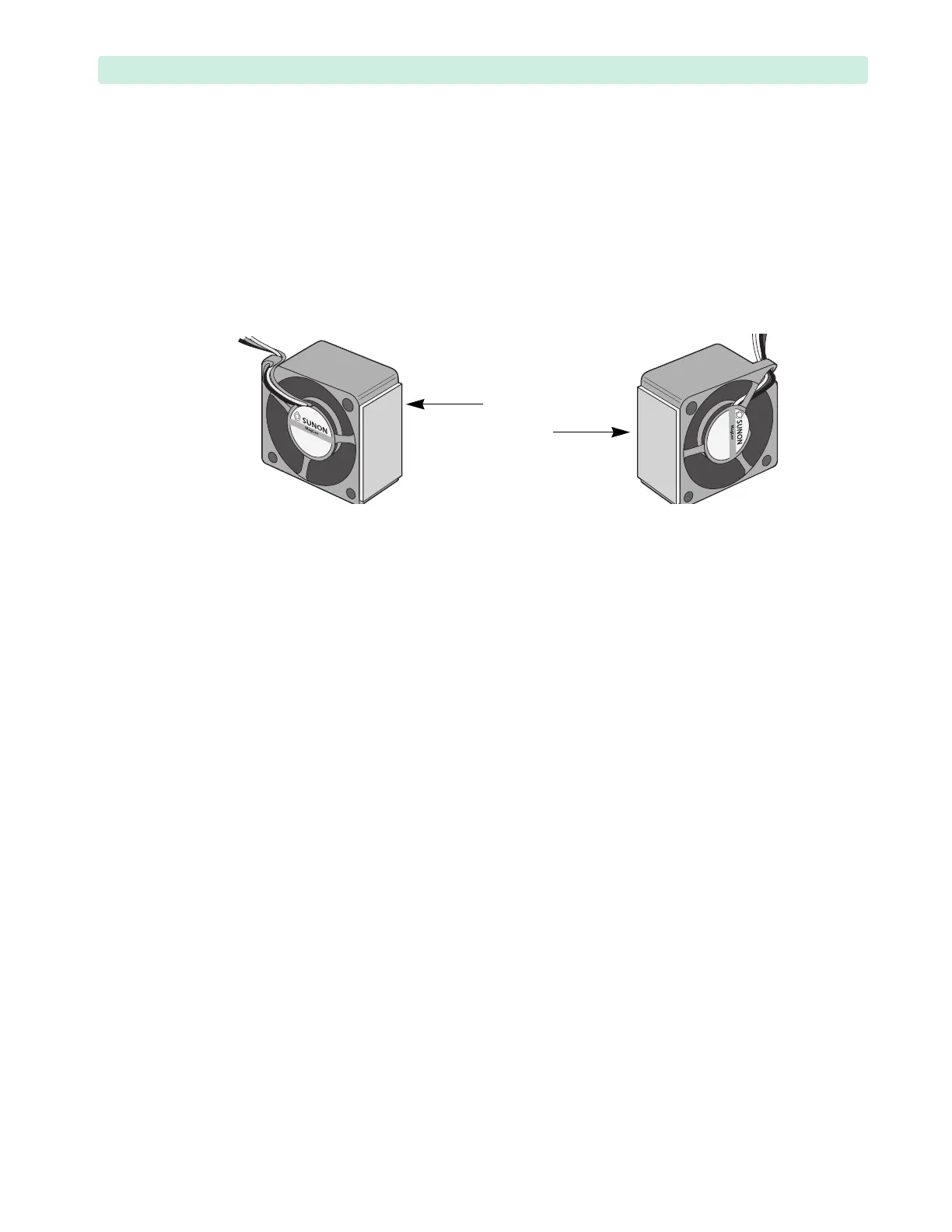
Use Figure 64 to determine the adhesive side of the Fan.
b Wipe the upper and lower Power Supply aluminum plates with 70% isopropyl alcohol wipes
and let them dry. Make sure alcohol does not drip into the device.
2 Reinstall the lower Fan first:
a Remove one side of the adhesive backing and secure it to the side of the lower Fan, as shown in
Figure 64 (lower Fan).
b Position the lower Fan, so that:
– the label on the Fan’s hub is facing away from the Capacitor Tray,
– adhesive pad is facing the Power Supply, and
– the braided bundle of Fan wires is facing you and away from the Power Supply.
– the Fan is flush with the Power Supply insulator sheet.
c Peel off the adhesives backing and install the Fan on the Power Supply sheet metal.
Press and hold the Fan in place for 10 to 20 seconds to secure it to the metal.
3 Secure the Rear Chassis in the upright Position, see “Tilting Rear Chassis” on page 91.
4 Repeat all sub-steps of Step 2 to reinstall the upper Fan.
5 Install the wires into the saddle clamps (see Figure 63):
a Install the lower Fan braided wire bundle into the lower saddle clamp.
b Install the upper Fan braided wire bundle into in three upper saddle clamps.
c Install the ECG Out 2-wire bundle into the three lower saddle clamps.
Route the ECG Out 2-wire bundle under the Battery Connection PCA and its wires.
d Install the Network cable into all four saddle clamps.
6 Thread both Fan braided wires through the Rear Chassis grommet.
7 Connect the Fan braided wires to the Therapy PCA in any order, see Figure 62 on page 102.
8 Ensure the connectors are fully seated.
9 Install the Rear Chassis Shelf. See “Rear Chassis Shelf” on page 93.
10 Close the device. See “Closing the Case” on page 151.
To Complete the Replacement:
Run Performance Verification and Safety testing as described in the “Performance Verification”
chapter.
Figure 64 Fan Adhesive Pads