4: Repair Internal Assemblies — Rear Chassis
112
Replacement:
1 Position the Therapy PCA in the Rear Chassis:
a Move all the wires aside.
b Align both plastic shields with the screw holes.
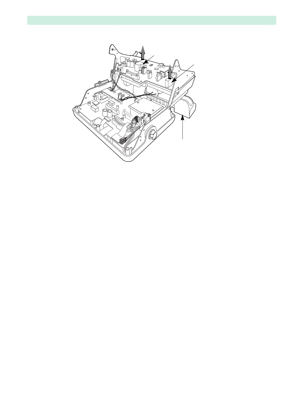
c Carefully but firmly grasp the positions K1 and T1 of the new Therapy PCA (see Figure 72)
and lower the Therapy PCA onto the Rear Chassis.
2 Secure the Therapy PCA with the ten T10 screws, see Figure 71,
➊ – ➓, to .
Note that the screws in positions
➍, ➎, ➏, ➑, and ➒ (standoff positions) are M3 x 14 mm, and the
remaining screws are M3 x 8 mm. See “Screw Usage” on page 70.
a Manually start the screws
➊ – ➓.
b Tighten the screws
➊ – ➓ to 6 inch-lb (0.7 N m). Use a criss-cross sequence, e.g.
➊-➓-➋-➒-➌-➑-➐-➍-➏-➎.
3 Thread both Fan wires (
➈, ➉) through the Rear Chassis grommet.
4 Thread the Therapy PCA Power Supply cable connector
➆ through the side opening of the Rear
Chassis as shown in Figure 73, and reconnect.
5 Reconnect cable connectors
➂, ➃, ➅ and ➇ – ➉, see Tab le 34 on page 110 and Figure 71 on
page 111.
The Fan wires (
➈, ➉) can be connected to J12 and J13 in any order.
6 Ensure the connectors are fully seated.
Figure 72 Therapy PCA Removal



 To Next Page