Internal Assemblies — Front Chassis 4: Repair
137
Replacement
1 Install the Clock Battery to the new Processor PCA, see “Clock Battery” on page 118.
2 Place the Processor PCA in position, see Figure 91 on page 136 and Figure 92 on page 137.
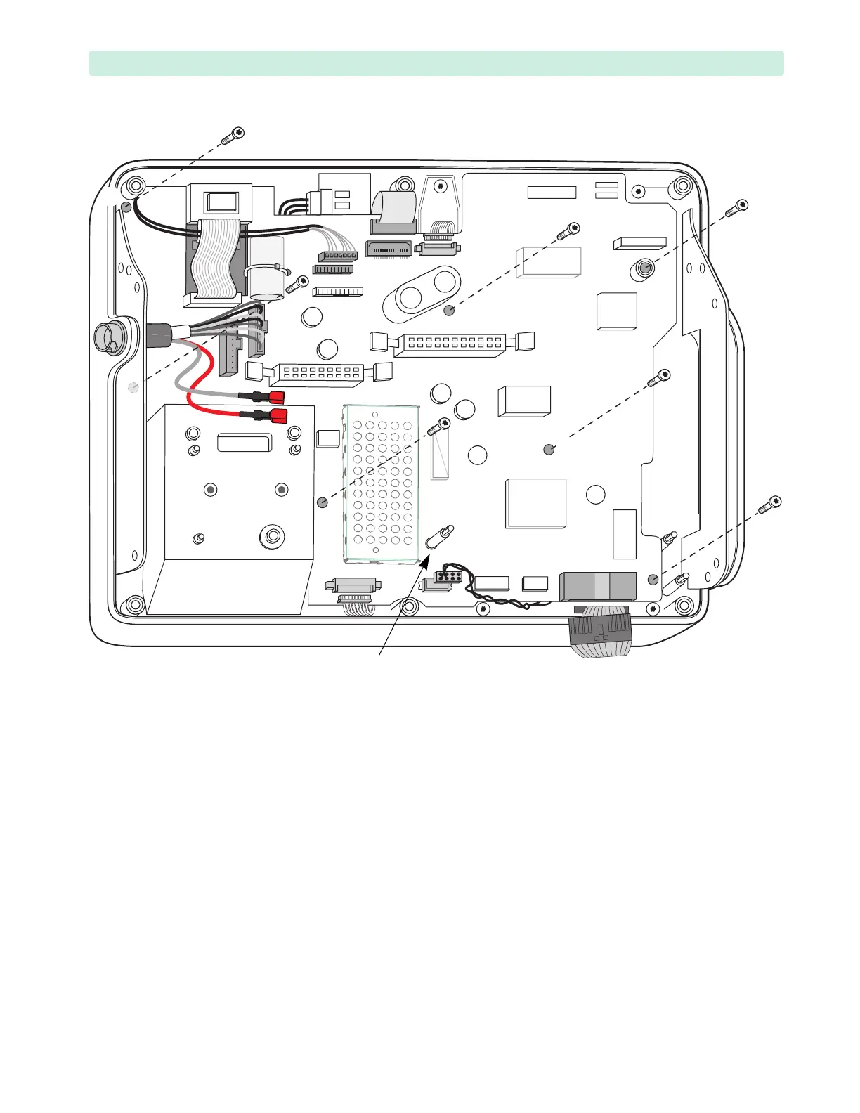
a Position an M3x8 (T10) screw in the Processor PCA difficult-to-access point
➋.
b Guide the cables
➀, ➂, and ➃ out of the way and the Therapy Switch ribbon cable ➁ through
the square opening in the Processor PCA.
c Guide the cables
➆, ➇, and ➈ out of the way and the Battery PCA standoff through the round
opening in the Processor PCA.
d Line up the holes in the Processor PCA with the threaded standoffs underneath. Make sure
there are no cables or wires trapped underneath the PCA.
3 Replace the seven M3x8 (T10) screws and tighten to 6 inch-lb (0.7 N m). See Figure 92. Note that
the screw
➌ is M3x16 mm, and the remaining screws are M3x8 mm. See “Screw Usage” on page 70.
4 Replace the Measurement Module. See “Measurement Module and the Ports” on page 128.
5 Connect cables
➀ – ➈, see Figure 91 on page 136 and Tab le 3 5 on page 135.
Connect cable
➂ before ribbon cable ➁.
Figure 92 Processor PCA Screws
➊
➋
➌
➍
➎
➏
➐
Battery PCA standoff