External Assemblies 4: Repair
79
Replacement
1 Position the device on the work surface with the rear side facing you.
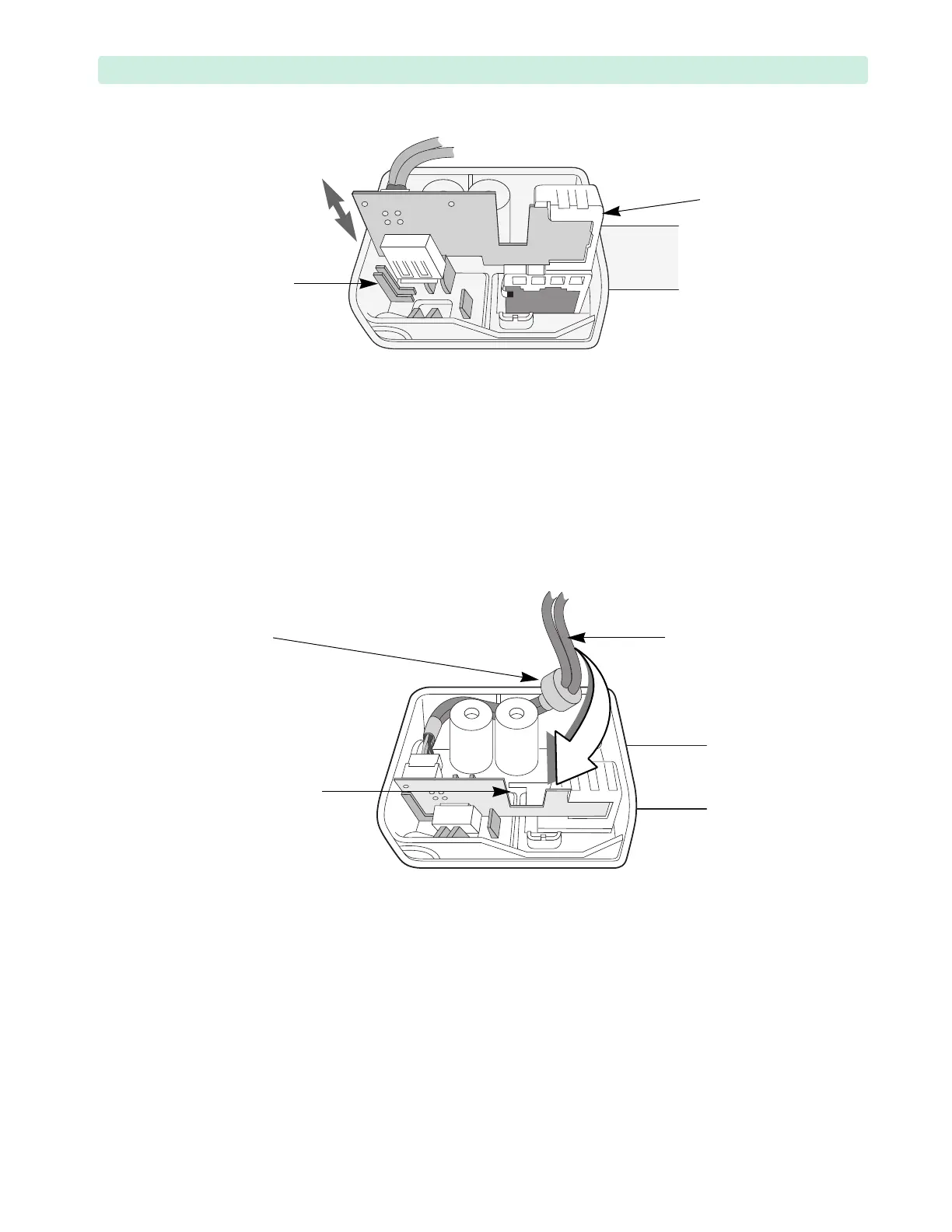
2 Use the guides inside the handle to insert the RFU-and-USB Assembly into the new Handle. See
Figure 39.
3 Make sure that both the mount and PCA are fully seated and flush with the Handle’s bottom.
4 Wrap the RFU-and-USB cable around the plastic standoffs and guide through the cut-out.
Slightly wiggle the ferrite core to make sure it fully fits into the handle. See Figure 40.
5 Align the Handle against the Front Case.
Make sure not to pinch wires between the Handle and the Front Case.
6 Replace the four M4x10 (T15) screws in the handle. Tighten the screws to 10 inch-lb. (1.1 N m).
To Complete the Replacement:
1 Visually inspect the device to ensure that you installed the handle assembly correctly.
2 Run Performance Verification and Safety testing as described in the “Performance Verification”
chapter.
Figure 39 Handle Replacement
Figure 40 RFU-and-USB Cable Inside the Handle
RFU-and-USB
cable cut-out
RFU-and-USB
cable
ferrite
core