RFC 4072S
124 / 272
PHOENIX CONTACT 108580_en_02
• Set the required safety parameters. In the example in Figure 4-46, these are F-Address
F_Dest_Add, watchdog time F_WD_Time, and the assignment of channels 1 and 2 of
the inputs.
If necessary, adapt the settings to your application.
• Under the “Profinet (x)” node in the “PLANT” area, double-click on the lower-level node
of the safety module whose safety parameters you want to set (in the example in
Figure 4-47 on page 124: AXL F PSDO8/3 1F).
The safety module editor group opens.
• Select the “Safety Parameters” editor.
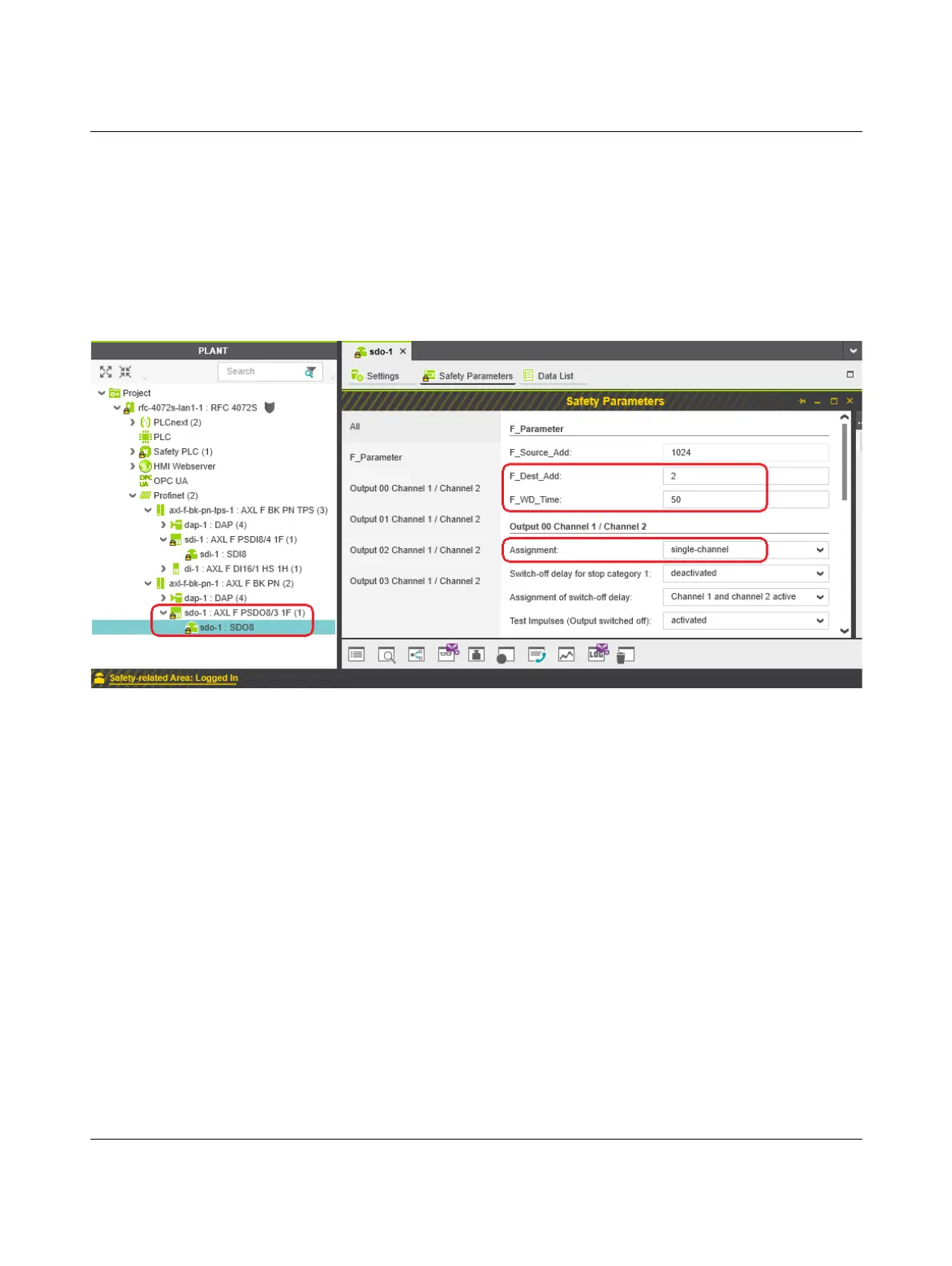
Figure 4-47 “Safety Parameters” editor: AXL F PSDO8/3 1F
• Set the required safety parameters. In the example in Figure 4-47, these are F-Address
F_Dest_Add, watchdog time F_WD_Time, and the assignment of channels 1 and 2 of
the outputs.
If necessary, adapt the settings to your application.
• Repeat the above safety parameter settings for each safety module used in your appli-
cation.
 Loading...


