RFC 4072S
44 / 272
PHOENIX CONTACT 108580_en_02
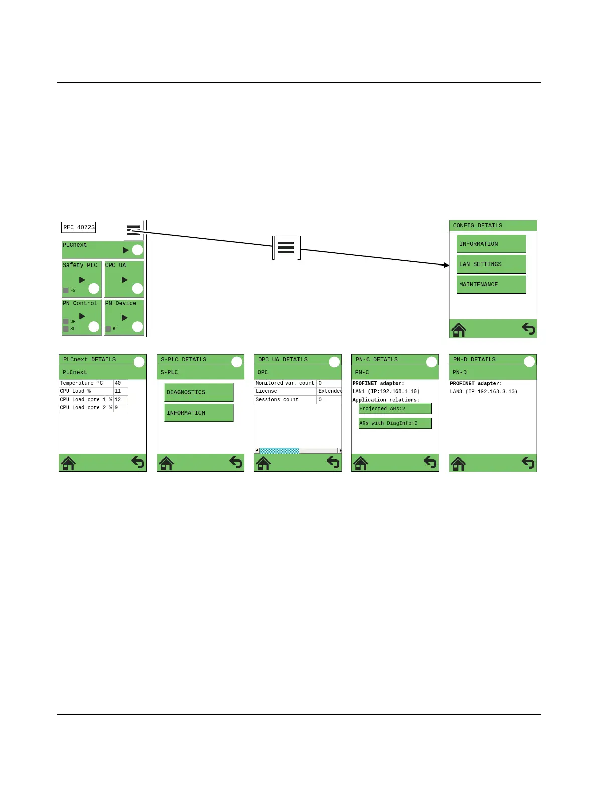
2.9 Structure of the display (diagnostic display)
The display contains important diagnostic and status information for the RFC and its inter-
faces. Depending on the selected view, more detailed information can be selected for indi-
vidual items. For example, the IP addresses of the RFC can be requested via the display
and set if necessary.
Possible indicators of the display are described below:
The following figure shows the structure of the display (home menu and submenus):
Figure 2-14 Structure of the display
Key:
A Home menu
B “CONFIG DETAILS” menu
C “PLCnext DETAILS” menu (standard controller)
D “S-PLC DETAILS” menu (safety-related iSPNS 3000 PROFINET controller)
E “OPC UA DETAILS” menu (OPC UA server)
F “PN-C DETAILS” menu (PROFINET controller)
G “PN-D DETAILS” menu (PROFINET device)
 Loading...


