RFC 4072S
30 / 272
PHOENIX CONTACT 108580_en_02
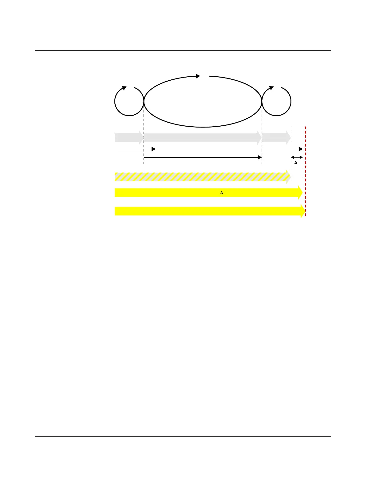
The following figure illustrates the relationship:
Figure 2-3 Simplified calculation of the SFRT response time
( *) = Not necessarily the output device
Key:
SFRT
max
Maximum permissible safety function response time of the
PROFIsafe system involved in the safety function that is deter-
mined for each safety function to be implemented.
SFRT Safety function response time of the PROFIsafe system involved
in the safety function and the RFC 4072S that is actually imple-
mented.
WCDT IN Worst case delay time of the F-Device with input function.
For this time, please refer to the device-specific user documen-
tation for the F-Device used.
F_WD_Time IN
max
Value of the monitoring time F_WD_Time (watchdog time) which
may be set as the maximum value for each individual F-Device
with an input function that is involved in the safety function in
order that SFRT
max
is not exceeded (see equation [2] page 31).
F_WD_Time OUT
max
Value of the monitoring time F_WD_Time (watchdog time) which
may be set as the maximum value for each individual F-Device
with an output function that is involved in the safety function in
order that SFRT
max
is not exceeded (see equation [2] on
page 31).
F_WD_Time IN + F_WD_Time OUT
max max
Output
Delay
Input
Delay
Worst Case
Delay Time (input)
Device WD Device WD
F_WD_Time IN + F_WD_Time OUT
max max
Worst Case
Delay Time (output)
t
107586A021
WCDT
IN
WCDT
OUT
Worst Case Delay Time
(processing and transmission)
Total Worst Case Delay Time = TWCDT
Safety Function Response Time SFRT (TWCDT + of the longest “Device WD Time” *) )t
Maximum Safety Function Response Time SFRT (determined via Safety Function)
max
 Loading...


