Description of the RFC 4072S
108580_en_02 PHOENIX CONTACT 45 / 272
2.9.1 Indicators on the display
The following figure shows the general meaning of the indicators in the home menu of the
display.
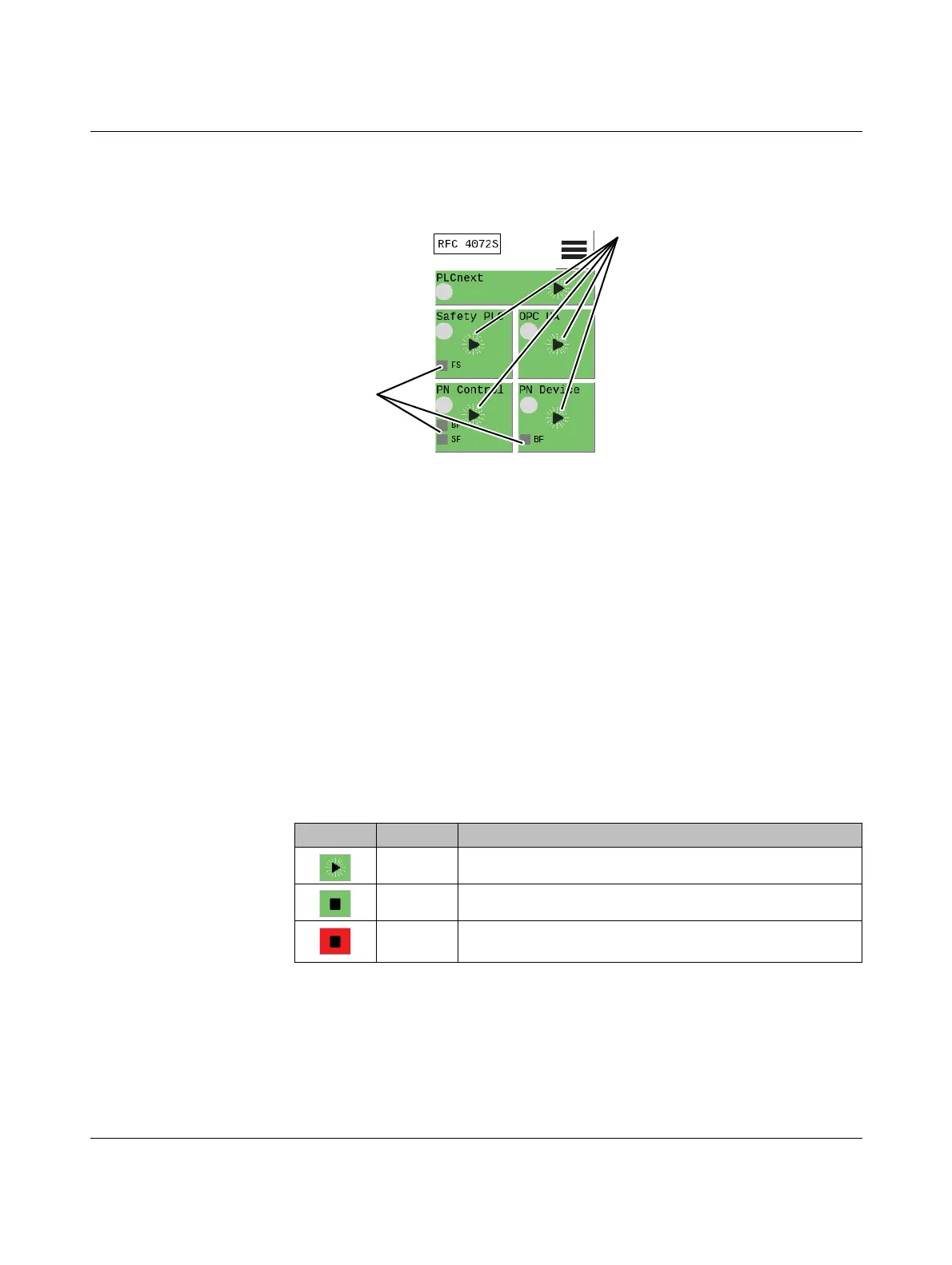
Figure 2-15 Display: indicators in the home menu
The diagnostic indicators (LEDs) and status information of the standard controller inside the
device, of the safety-related iSPNS 3000 PROFINET controller inside the device, and of the
OPC UA server are displayed on the individual tiles A to E in Figure 2-15. In addition, the
diagnostic indicators (LEDs) and status information of the RFC as a PROFINET controller
and/or PROFINET device are displayed.
The background color in the individual areas varies depending on the states.
2.9.2 Status information
The status information of the individual tiles is displayed only in the home menu. The back-
ground color on the individual tiles varies depending on the state.
The status information on the individual tiles has the following meaning:
PLCnext (standard
controller)
A: PLCnext (standard controller)
B: Safety PLC (iSPNS 3000)
C: OPC UA (OPC UA server)
D: PN Control (PROFINET controller)
Status information for:
Diagnostic
indicators:
LEDs
E: PN Device (PROFINET device)
A
B
C
DE
Table 2-2 Status information: PLCnext (standard controller)
Indicator Color Meaning
Green The standard controller is in the “Run” state.
Green The standard controller is in the “Stop” state.
Red The standard controller has switched to the “Stop” state as a
result of an error.
 Loading...


