Startup and validation
108580_en_02 PHOENIX CONTACT 91 / 272
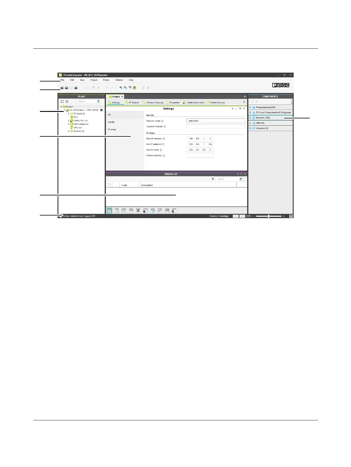
4.4.4 User interface
Figure 4-2 PLCnext Engineer user interface
1. Menu bar
2. Tool bar
3. “PLANT” area
4. Editors area
5. “COMPONENTS” area
6. Cross-functional area
7. Status bar
“PLANT” area All of the physical and logical components of your application are mapped in the form of a
hierarchical tree structure in the “PLANT” area.
Editors area Various color-coded editor groups can be shown in the editors area. To do this, double-click
in the relevant area. The color coding distinguishes an instance editor (green, “PLANT”
area) from a type editor (blue, “COMPONENTS” area), for example.
“COMPONENTS” area The “COMPONENTS” area contains all of the components available for the project. The
components are subdivided according to their function.
Cross-functional area The cross-functional area contains functions that extend across the entire project (e.g.,
ERROR LIST, WATCHES, LOGGING, and RECYCLE BIN).
 Loading...