Chapter 3 Calibration
Revision W HF Series X-ray Generators - Service Manual
3-40 Quantum Medical Imaging, LLC
WARNING! To avoid injury to personnel, ensure
system power is removed prior to making and
removing any electrical connections.
1. If using a Dynalyzer, a kVp bleeder tank should be connected in series
between tube and High-Voltage (H.V.) Transformer A17.
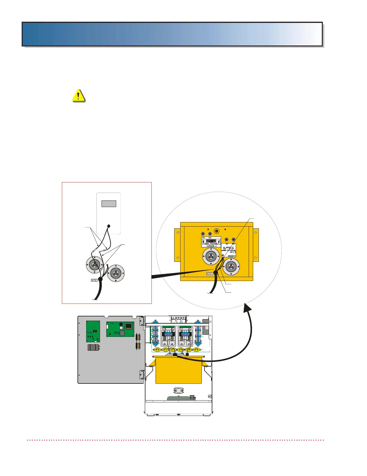
2. If using a mAs meter, remove two (2) green/yellow wires marked "MAS
METER", connected to A17P1-9 and A17P1-10, from the ground stud on
top of the H.V. Transformer (see Figure 3-32). Connect the mAs meter in
series between removed wires. The MAS meter should remain connected
throughout calibration. (
Important: These wires must be re-connected
when finished calibration.
)
Figure 3-32. MAS Meter Connection
MAS METER
GREEN/YELLOW
WIRES (2X)
MAS METER
LEADS
HIGH VOLTAGE
TANK A17
(AY20-031 or
AY20-032)
GENERATOR CABINET
(PCB DOOR OPEN)
MAS METER CONNECTION
STUD
CONNECTOR
A17P1
GREEN/YELLOW
WIRES (2X)
H.V. TANK
(TOP VIEW)
 Loading...