Chapter 5 Service Instructions
HF Series X-ray Generators - Service Manual Revision W
Quantum Medical Imaging, LLC
5-11
Anode Volt
(Cont’d)
6. Verify AC line voltage meets speci-
fication during an exposure: Check
capacitor voltage (C9-C12 and
C13-C16 on single-phase units,
C1-C4 on SE units, or C9-C12 and
C13-C16 on three-phase units) is
between +350 and +440 VDC.
The power must be sufficient to
support the exposure (i.e., check
for weak AC Line).
7. Verify that all grounds are good
(JP2-JP9 installed or shorted on
Logic Board A1 (AY40-006S)).
APR Tree
Load Error
{text
string}
An error occurred while loading
the APR tree. Note: {text string}
will contain additional details.
Call Technical Service/Support.
Backup Backup time was reached based
on current technique factors.
1. Reduce technique factor(s). Re-
take exposure.
2. Verify ion chamber cable connec-
tions are correct and secure.
3. On AEC Control Board A11
(AY40-031S or AY40-027S), check
+15 VDC and -15 VDC outputs are
not loaded down. If so, remove ion
chamber cable connection and re-
check voltages. If +15 VDC and /or
-15 VDC outputs are now good, ion
chamber is at fault. If still loaded
down, replace AEC Control Board.
4. Verify the Backup Time/mAs set-
tings in APR view (if caused during
APR mode) and/or Backup Time/
mAs in Service Settings configura-
tion screen are set correctly (i.e.,
not too low).
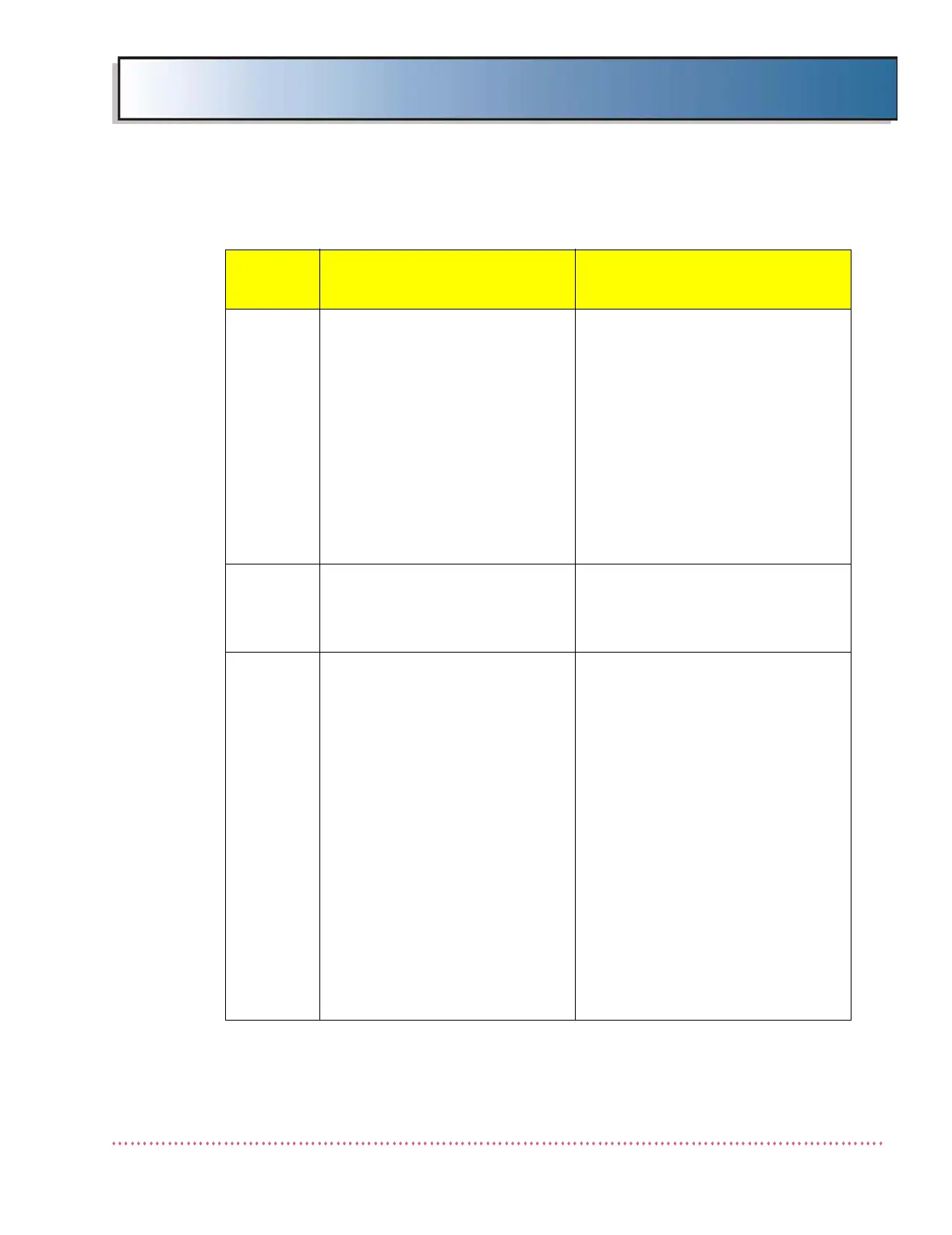
Table 5-1. Error Messages and Possible Cause(s)
Error
Message
Possible Cause(s)
Remedial Action
 Loading...