Chapter 5 Service Instructions
Revision W HF Series X-ray Generators - Service Manual
5-10 Quantum Medical Imaging, LLC
4. Re-connect cable plugs to connec-
tors J7 and J8 on KVP Control
Board A2.
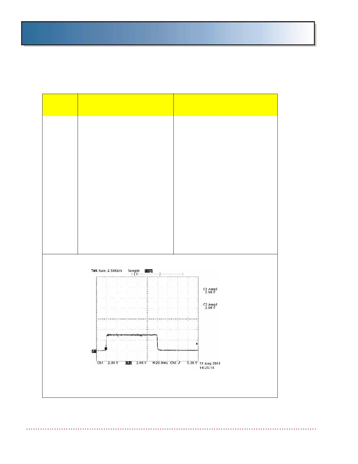
5. On KVP Control Board A2, con-
nect oscilloscope probe to A2TP1
(Anode Sense) and take an expo-
sure. A short exposure and error
message will occur. Waveform
should be as shown below: The
equivalent kV value should be
approximately half the indicated
kV value on OCP (e.g., 25 kV for
50 kV setting on OCP). If kV value
is acceptable, check H.V. Trans-
former. If value is not correct,
replace KVP Control Board A2
(may be faulty A/D Converter). If
problem still exists, replace Logic
Board A1 (AY40-006S).
Sample waveform above is with operator control panel set for 50 kVp, 200L mA, 100 ms.
(Each volt measured represents 8.2 kV.) If spikes are present, this indicates arcing in
either the x-ray tube or high voltage transformer.
Table 5-1. Error Messages and Possible Cause(s)
Error
Message
Possible Cause(s)
Remedial Action
 Loading...