Chapter 5 Service Instructions
HF Series X-ray Generators - Service Manual Revision W
Quantum Medical Imaging, LLC
5-19
Generator
Comms
Operator Control Console lost
communication with generator
cabinet. Can be caused by:
1. Faulty or improperly installed
OCP Serial Cable
2. Non-Q-Connect Systems only:
Improperly configured jumpers
on OCP Control Board A16
(AY40-004S1) or Logic Board
A1 (AY40-006S)
3. Failed transceivers on A1 and/
or A16 boards.
4. Logic Board A1 microproces-
sor A1U9 faulty, not properly
seated in socket, or loaded with
incorrect program.
5. +5 VDC supply to Logic Board
A1 too low.
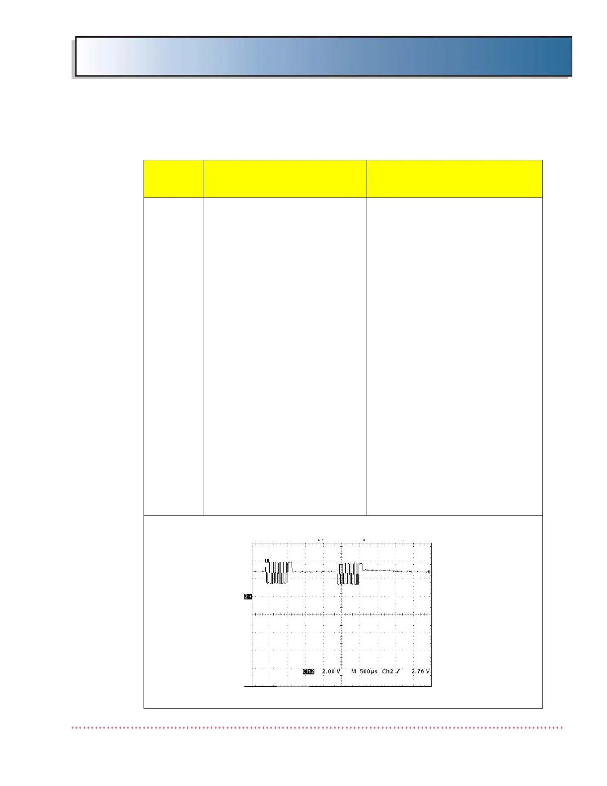
Non-Q-Connect Systems only: On
OCP Control Board A16 (AY40-
004S1), connect oscilloscope to test
point TP2. With system turned on
and idling, verify waveform is as
shown below. There should be a set
of two pulses approximately every
second. The first pulse is sent from
the OCP Control Board to the Logic
Board. The second pulse is sent by
the Logic Board to the OCP Control
Board in response to the first pulse.
If only one pulse is present, connect
oscilloscope to test point TP8 on
Logic Board A1 (AY40-006S). If no
pulse is present, OCP Serial Cable is
faulty or not connected properly.
Note: Verify jumpers A16JP1,
A16JP4, A16JP10, and A16JP11 are
installed on OCP Control Board.
Using DMM, measure dc voltage at
test point A1TP1. If less than +5
VDC, check for blown fuse F8 on
Interface Board A9 (AY40-023T).
Replace fuse if necessary.
Table 5-1. Error Messages and Possible Cause(s)
Error
Message
Possible Cause(s)
Remedial Action
 Loading...