Appendix D Calibration (Using Generator Service Tools)
HF Series X-ray Generators - Service Manual Revision W
Quantum Medical Imaging, LLC D-27
3. Select Next to proceed with the first voltage calibration, or you may
select a particular voltage level to calibrate by touching its corresponding
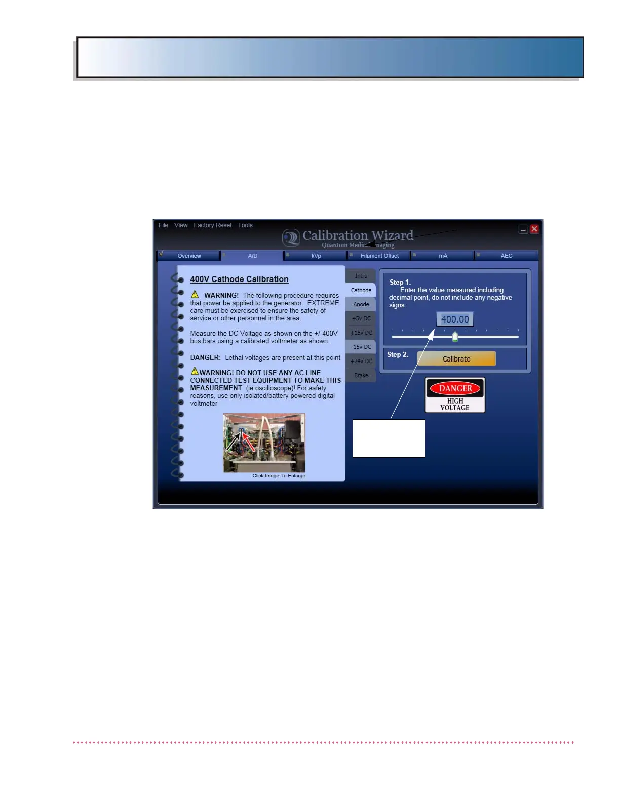
tab (choices are Cathode, Anode, +5 VDC, +15 VDC, -15 VDC, +24 VDC
(Regulated), and Brake (unregulated +24 VDC). For this example, "Cath-
ode" is selected, as shown below.
Figure D-15. Sample A/D Voltage Calibration Screen (400V Cathode is shown)
4. Refer to Table D-1 and connect a voltmeter to the test point correspond-
ing with the voltage level selected for calibration.
5. On the voltmeter, observe the measured voltage value. Enter the actual
(measured) value by adjusting the slide control, or by selecting the data
entry box and typing the value using a keyboard. The value entered
should be to the hundredths decimal place. Press Calibrate button.
6. Ideally, the value appearing in the 400V Cathode Calibration Screen (Step
1.) will match the reading on the voltmeter within its allowable tolerance.
If so, press the Confirm button. The Calibration value is saved and the
system advances to the next uncalibrated A/D voltage. If not the same,
press Repeat and re-enter the measured voltage value.
ENTER VOLTAGE
READING FROM
METER
 Loading...