Chapter 6: Replacements ABL77 Service Manual
Valve Board, Continued
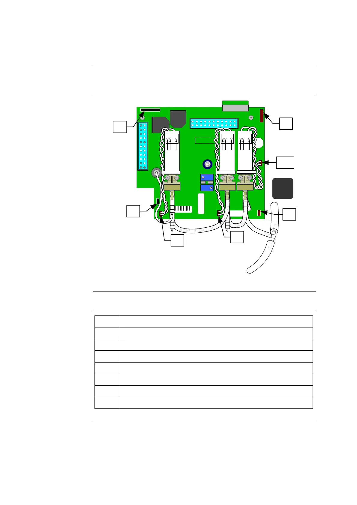
Valve board
diagram
The following diagram shows the wiring connections of the current design valve
board.
41449 / B
41477
SERVICE BOARD ABL70-77
ASSY REV :
K1
J5
R2
R18
REVISION
J10
PN 902-811
J1
J9
SENSOR BOSS
SENSOR
LUER
J6
J4
J8
J7
J3
12 1
13 24
J2
2587
J6
J5
J4
J9
J8
J7
L2 L1 L3
J10
L3
COM
N.C.
N.O.
L1
COM
N.C.
N.O.
L2
COM
N.C.
N.O.
J5
↑
J4
J6
J7
J8
J9
J10
Figure 6-8
Items and
descriptions
The following table describes the cable connections in figure 6-8.
Item Function
J4 Waste pump cable connection
J5 Roller pump cable connection
J6 Opto-sensor cable connection
J7 Former valve L3 connection
J8 Valve L1 connection
J9 Valve L2 connection
J10 New valve L3 connection
Continued on next page
6-16 Rev. F

 Loading...