Home
RADIOMETER
Measuring Instruments
ABL 77 Series
RADIOMETER ABL 77 Series User Manual
4
of 1
of 1 rating
355 pages
Give review
Manual
Specs
To Next Page
To Next Page
To Previous Page
To Previous Page
Loading...
ABL77 Service Manual
Chapter 7: Re-Assembly
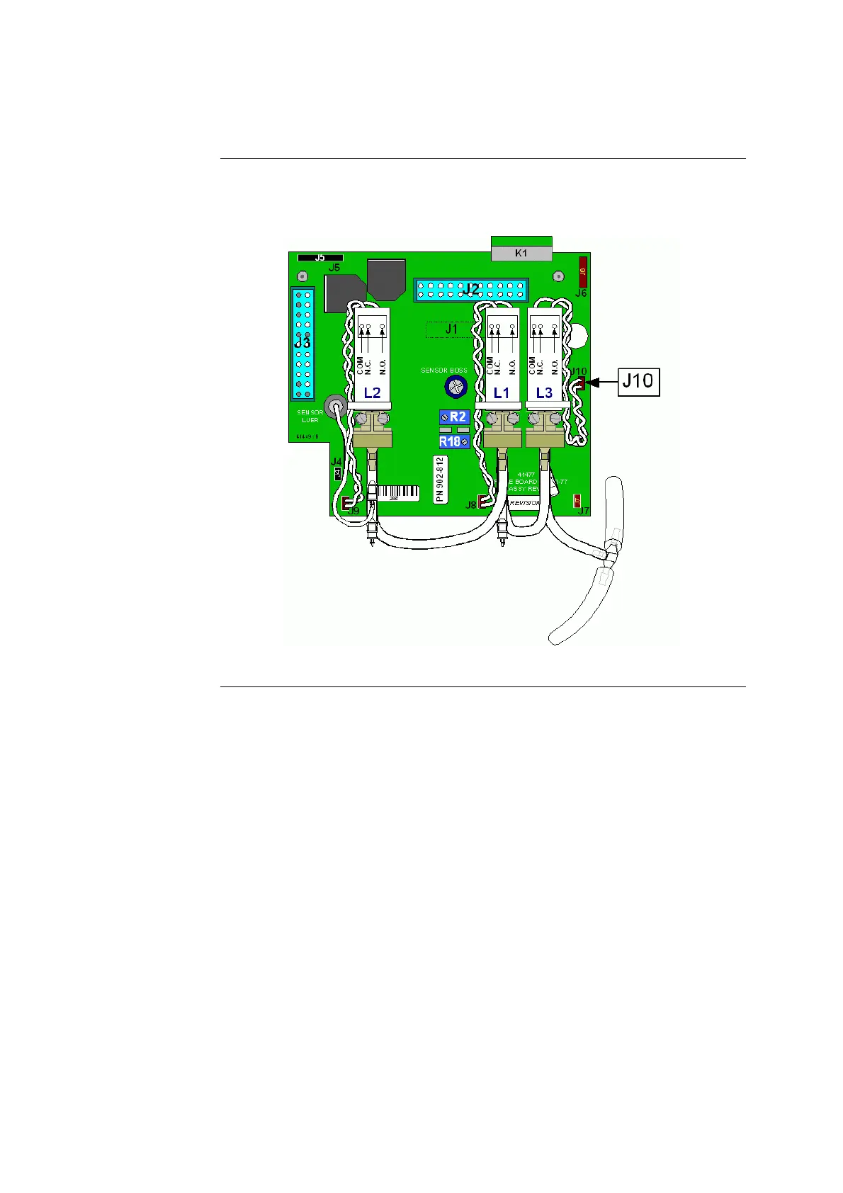
Valve Boards – General Information,
Continued
Surface-mount
valve board
The current valve board uses a surface-mount
design to take advan
tage of more
advanced technology (902-812). This valve board also has a J10 connector in a
more convenient location, Figure 7-9.
Figure 7-9
Rev. F
7-19
269
271
Table of Contents
Default Chapter
3
Table of Contents
3
Introduction
9
Service Policy
10
Test Equipment and Tools
13
ABL77 Identification
14
Panel Options
15
Analyzer Description
16
Overview
16
Functional Description
17
Chapter 2 : Analyzer Description
17
Overview
17
Sci Installation
18
Calibration
20
Sample Analysis
27
Module Descriptions
33
Upper Module
41
Lower Module
45
Electronics Module
49
Overview
61
General Information
62
Chapter 3 : Troubleshooting
63
Cautions and Warnings
63
General Guidelines
64
Hardware Screen
65
Reference Table of Problems, Causes and Corrective Actions
68
Reference Table
69
System Messages
76
Test and Calibration Procedures
89
Overview
89
Chapter 4 : Test and Calibration Procedures
91
Verify the Fluid Transport System
91
Calibration Lines Procedure
93
Testing the Valve Connections
99
Valve Test Procedures
101
Check Valve Fluidics System
103
Original Fluidics System
107
Waste Line
114
Volt Power Output Setting
117
Sc/Hematocrit Circuits
119
Electronic Zero Offset
122
Heater Circuit
124
Inlet Flap Sensor
127
Paper Jam
128
Battery Charger
131
Battery Pack
133
Touch Screen Panel Calibration
136
Reprogramming the CPU BIOS Settings
138
Re-Programming the Barcode Scanner
140
Resetting the Analyzer Serial Number
144
Dismantling
145
Overview
145
Overview
147
Chapter 5 : Dismantling
148
Upper Module
148
Backlight Inverter Board
151
Disk Drive
152
LCD Display
154
Touch Screen Panel
156
Lower Module
157
Printer Door
157
Printer Module
158
Lower Module
160
Opto-Sensor
163
Roller Wheel and Roller Pump
164
Waste Pump Head and Waste Pump
166
Original Valve Board / Manifold Assembly
169
Valve Board with Replaceable Valves
171
Valve Board Styles
175
Electronics Module
179
Analog Board
182
Interface Board
184
Power Distribution Board
186
Electronic Boards Assembly
188
LCD Adapter Board
189
Memory Module
190
Chipdisk Board
191
CPU and Touch Screen Boards
192
CPU or Touch Screen Boards
192
Battery Control Board
193
Fan Assembly
195
Replacements
196
Overview
196
Overview
198
Chapter 6 : Replacements
199
Main Housing
199
Main Housing Assembly
199
Carrying Handle
200
Upper Module
201
Housing Bracket
201
Lower Module
204
Manifold Gasket
204
Valve Board
205
Single Valve
213
Valve Board Tubing
217
Manifold
221
Electronics Module
224
Coin Cell Battery
224
Rear Panel
225
Battery
226
Continued on Next Page
228
Cabling
228
Disk Drive Cable
231
LCD Display Cable
233
Backlight Inverter Cable
235
Touch Screen Cable
237
Main Analog Cable
238
Analog Power Cable
239
Power Board Cable
240
A/D Cable - Analog Board to CPU Board
242
Printer Data Cable
243
Printer Power Cable
244
A/D Cable - Analog Board to Battery Control Board
245
COM1 Cable
247
Power Switch Cable
248
Barcode Reader / Keyboard Cable
249
Ethernet Cable
251
Re-Assembly
252
Overview
252
Chapter 7 : Re-Assembly
255
Upper Module
255
Touch Screen Panel
256
LCD Display
259
Disk Drive
260
Backlight Inverter Board
263
Upper Module
264
Lower Module
266
Valve Boards - General Information
266
Valve Board Assembly
271
Waste Pump and Waste Pump Head
275
Roller Pump and Roller Wheel
278
Opto-Sensor
282
Lower Module
283
Printer Module
286
Printer Door
287
Electronics Module
288
Rear Panel Assembly
288
Fan Assembly
289
Electronics Chassis and Battery Cage
290
Battery Control Board
291
Electronics Shelf
293
Electronic Boards
295
Touch Screen and CPU Boards Assembly
297
Chipdisk Board
298
Memory Module
299
Disk Drive Cable
300
LCD Adapter Board
301
Electronics Boards - Module Assembly
302
Electronic Boards - Module Assembly
302
Power Distribution Board
305
Interface Board
307
Analog Board
309
Electronics Module
313
Maintenance
315
Overview
315
Chapter 8 : Maintenance
316
Valve Maintenance
316
Cleaning
320
Long-Term Storage
323
Recommended Service Procedures
327
1-Year Service
327
2-Year Service
328
3-Year Service
329
Spare Parts
332
Chapter 9 : Spare Parts
332
Modules and Externals
332
Upper Module Components
334
Lower Module Components
336
Main Housing
342
Electronics Module Components
345
Recommended Parts and Hardware
351
Continued on Next Page
351
4
Based on 1 rating
Ask a question
Give review
Questions and Answers:
Need help?
Do you have a question about the RADIOMETER ABL 77 Series and is the answer not in the manual?
Ask a question
RADIOMETER ABL 77 Series Specifications
General
Brand
RADIOMETER
Model
ABL 77 Series
Category
Measuring Instruments
Language
English
Related product manuals
RADIOMETER ABL90 FLEX
346 pages
RADIOMETER ABL800 FLEX
438 pages

 Loading...