Managing scanner device with R&S TSME Device Manager
R&S
®
TSMA6
189User Manual 4900.8057.02 ─ 11
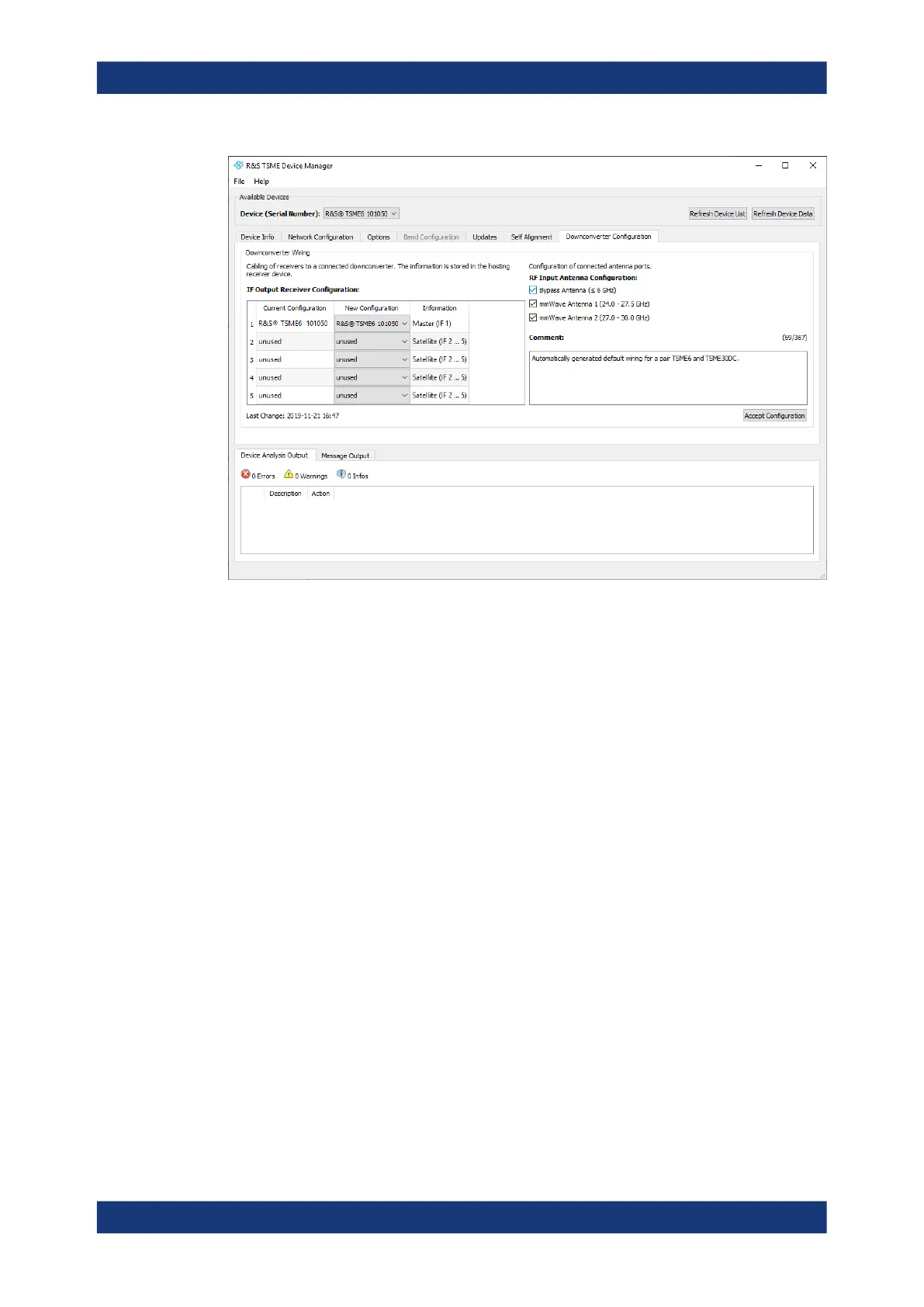
Figure C-5: Tab "Downconverter Configuration"
IF Output Receiver Configuration
Specify the configuration of the IF output connectors of the R&S TSME30DC/
TSME44DC.
RF Input Antenna Configuration
●
Specify the configuration of the RF input antenna connectors of the R&S
TSME30DC.
– Bypass Antenna (< 6 GHz)
– mmWave Antenna 1 (24 GHz to 27.5 GHz)
– mmWave Antenna 2 (27 GHz to 30 GHz)
For R&S ViCom and R&S ROMES, the API only allows the configuration of fre-
quencies of activated antenna ports. For the overlapping frequency range 27 GHz
to 27.5 GHz, the "mmWAve Antenna 1" is used by default.
●
Specify the configuration of the RF input antenna connectors of the R&S
TSME44DC.
– Bypass Antenna (< 6 GHz)
– mmWave Antenna 1 (24-44 GHz)
For R&S ViCom and R&S ROMES, the API only allows the configuration of fre-
quencies of activated antenna ports.
Accept Configuration
To confirm the current configuration settings, select the "Accept Configuration" button.
Configuring downconverter R&S TSME30DC/TSME44DC - "Downconverter Configuration"
 Loading...