Measurement Setup
R&S
®
TSMA6
63User Manual 4900.8057.02 ─ 11
7 Measurement Setup
7.1 Vibration-proofed stacking
7.1.1 Cascading R&S TSMA6/6B and R&S TSME6
To connect R&S TSMA6/6B and R&S TSME6
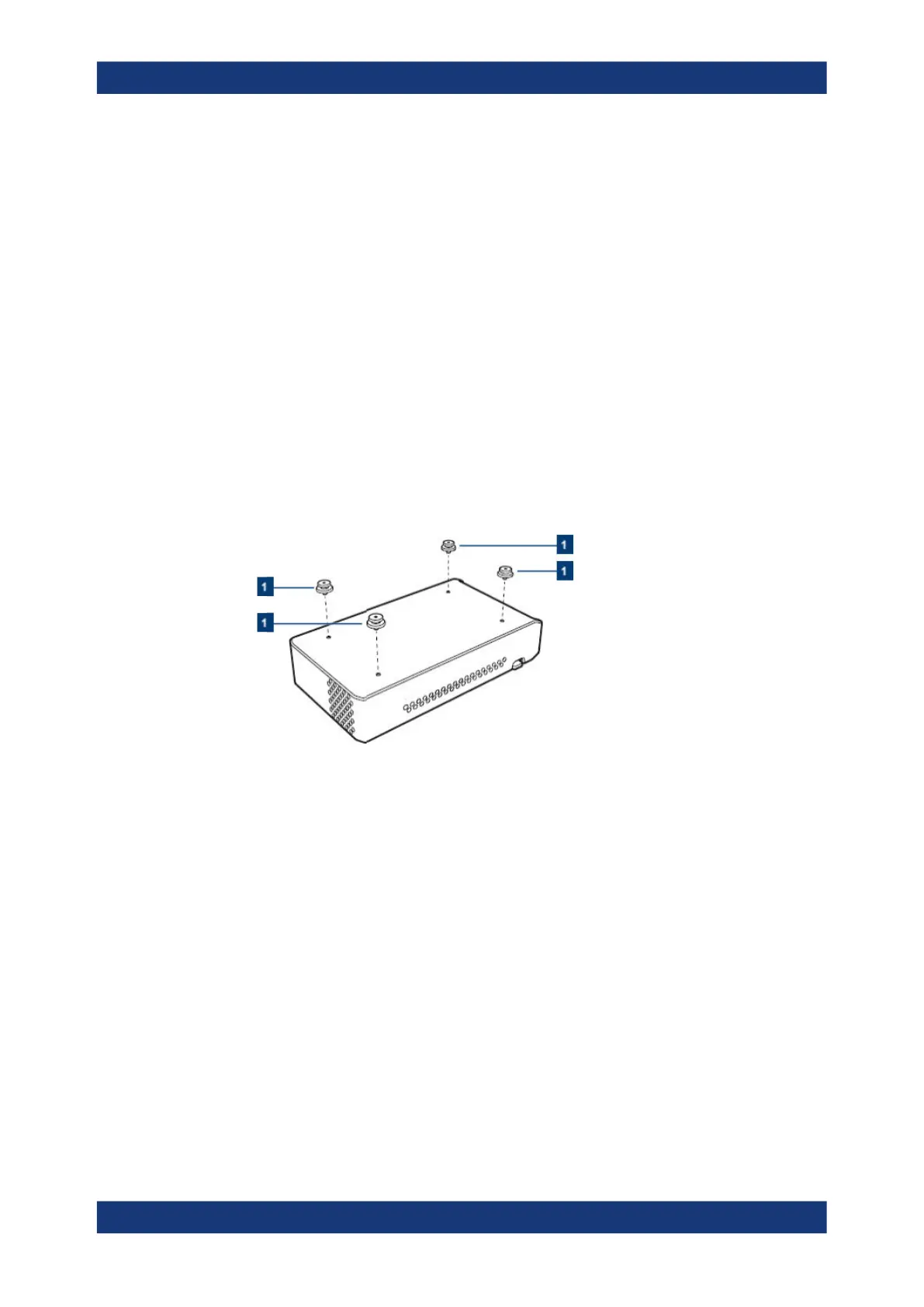
1. Screw the connecting elements (order no. 4900.0804.00) on the top of the R&S
TSMA6/6B.
● Torque: 0.66 Nm ± 0.05 Nm
● Secure with liquid plastic
Figure 7-1: Connecting elements
1 = Connecting elements (order no.4900.0804.00)
2. NOTICE! An insufficient airflow can cause the instrument to overheat, which may
disturb the operation and even cause damage. Make sure that all fan openings are
unobstructed and that the airflow perforations are unimpeded, particularly when the
instrument is installed in a rack or packed in a backpack. Ensure that the following
surrounding spaces to the instrument are kept clear:
● Front pane: minimum 2 cm
● Left/right panes: minimum 1 cm
Align the connecting elements with the holes on the bottom of an R&S TSME6 and
press the R&S TSME6 down.
Vibration-proofed stacking