Measurement Setup
R&S
®
TSMA6
67User Manual 4900.8057.02 ─ 11
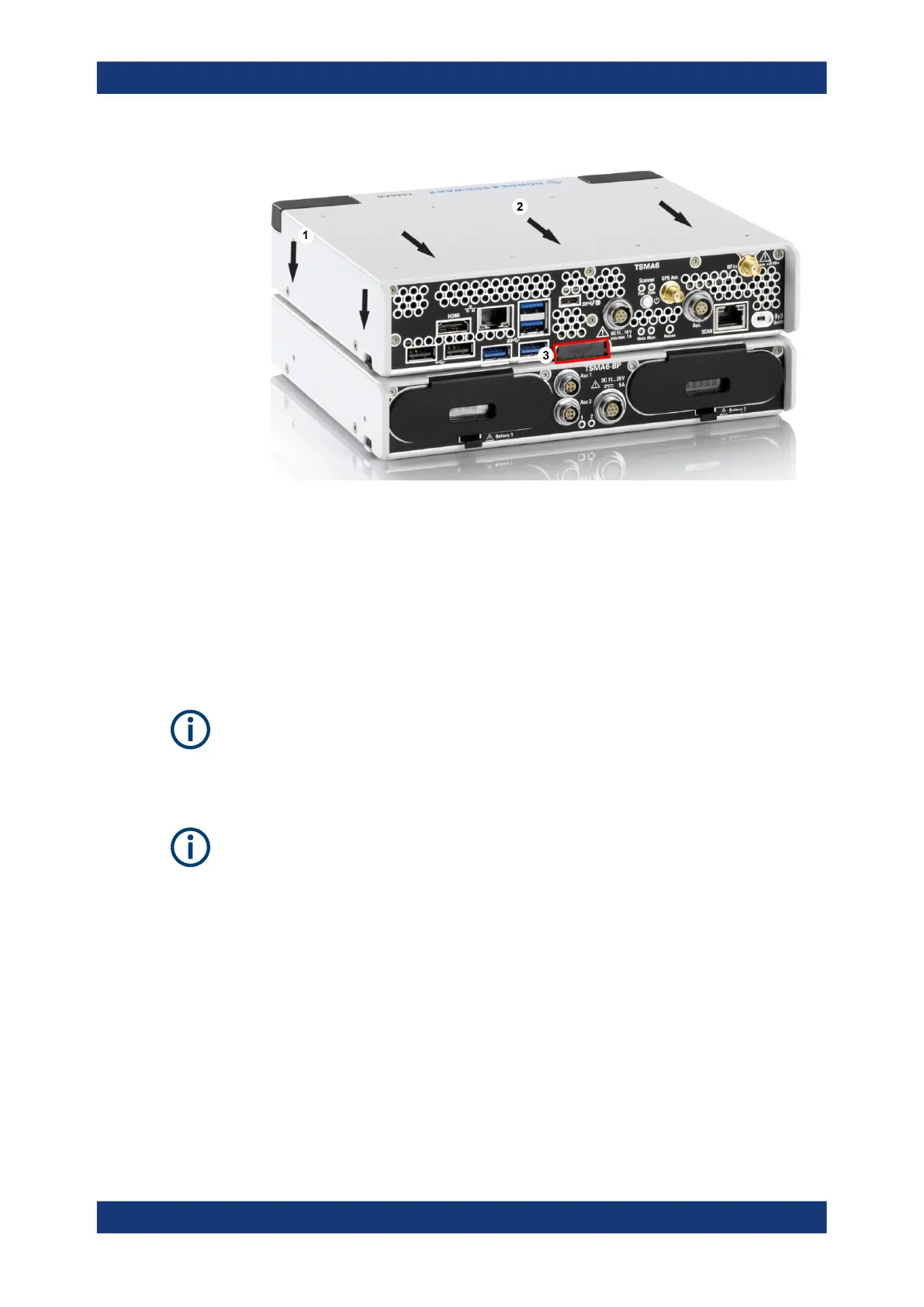
Figure 7-5: Connected R&S TSMA6/6B and R&S TSMA6-BP
1 = Attach R&S TSMA6 to R&S TSMA6-BP
2 = Move R&S TSMA6/6B to the rear side
3 = Power connection established (docking connector is snapped in)
7.1.3 Connecting R&S TSMA6/6B-BP with R&S TSME6 and R&S
TSMExxDC/TSMS53DC
The following steps are valid for R&S TSME6 and downconverter R&S
TSMExxDC/R&S TSMS53DC.
For the cabling of the devices, the accessory cables R&S TSMA6-BPPT or R&S
TSMA6-BP2T are necessary.
Additional cabling may be necessary for proper operation. For complete cabling
instructions, refer to the R&S TSME6 user manual and the R&S TSMExxDC/
R&S TSMS53DC manual.
1. Screw the collar screws (1) on the top of the R&S TSMA6/6B-BP with a Torx 8
screw driver.
● Torque: 0.66 Nm ± 0.05 Nm
Vibration-proofed stacking