Measurement Setup
R&S
®
TSMA6
68User Manual 4900.8057.02 ─ 11
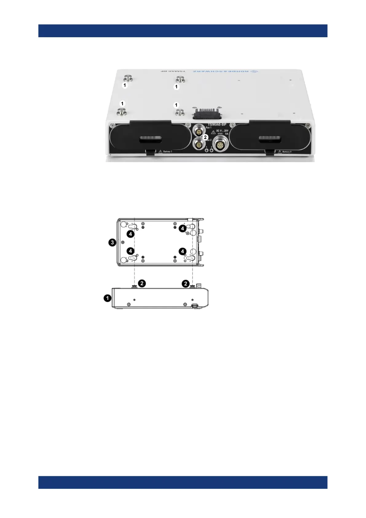
1 = Collar screws for connecting R&S TSME6
2 = Aux 1 / Aux 2 (auxiliary power out for connecting R&S TSME6/TSMExxDC/TSMS53DC via power
cable R&S TSME-ZYC)
2. Align the collar screws with the snap-in holes on the bottom of an R&S TSME6/
TSMExxDC/TSMS53DC and press the device down.
Figure 7-6: Example: Aligning R&S TSMA6/6B-BP and R&S TSME6
1 = R&S TSMA6/6B-BP
2 = Collar screws
3 = R&S TSME6/TSMExxDC/TSMS53DC
4 = Snap-in holes on the bottom pane of R&S TSME6/TSMExxDC/TSMS53DC
3. Move the R&S TSME6/TSMExxDC/TSMS53DC to the back side, until you hear a
click when the collar screws are locked in.
Vibration-proofed stacking
 Loading...