Measurement Setup
R&S
®
TSMA6
69User Manual 4900.8057.02 ─ 11
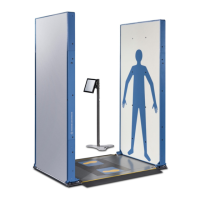
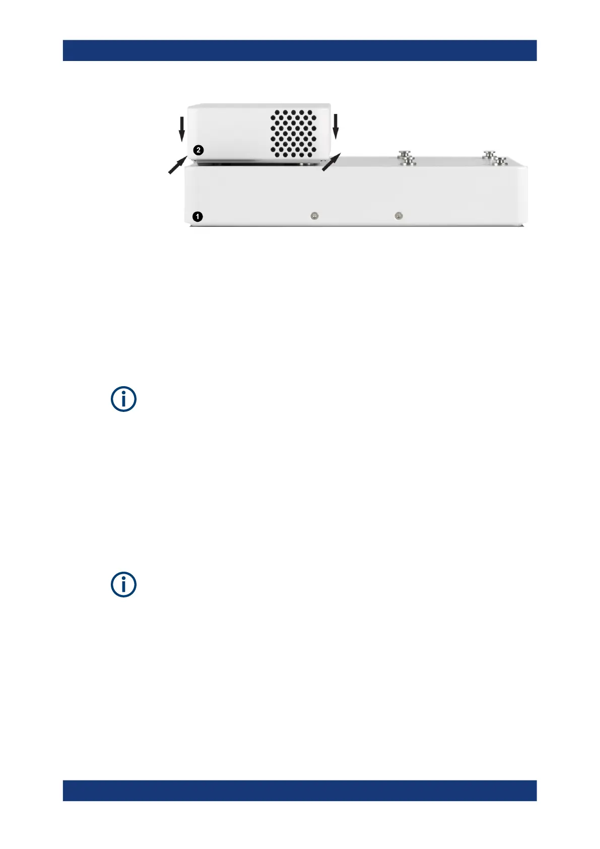
Figure 7-7: Connected R&S TSME6/TSMExxDC/TSMS53DC and R&S TSMA6/6B-BP
1 = R&S TSMA6/6B-BP
2 = R&S TSME6/TSMExxDC/TSMS53DC
4. Connect the power cable R&S TSMA6-BPPT resp. R&S TSMA6-BP2T from AUX1
resp. AUX2 to DC IN of R&S TSME6/xxDC/TSMS53DC (see Figure 7-9).
7.1.4 Connecting the R&S TSMA6 with multiple devices
Additional cabling may be necessary for proper operation. For complete cabling
instructions, refer to the R&S TSME6 User Manual and the R&S TSMExxDC Getting
Started.
The R&S TSMA6 can be connected with several devices at the same time. In the fol-
lowing, examples for such multiple device combinations are shown.
The connection of up to 4 R&S TSME6/TMSExxDC devices is possible.
●
For up to 2 devices, 1 x R&S TSMA6-BP2T dual power cable or 2 x R&S TSMA6
BPPT single power cables are required.
●
For up to 4 devices, 2 x R&S TSMA6-BP2T dual power cables are required.
Per device, 4 collar screws are required.
4 collar screws are part of the standard accessory of the R&S TSMA6. Additional collar
screws are part of the R&S TSME6/TSMExxDC accessory or can be ordered as spare
parts (R&S no. 4900.0804.00).
Vibration-proofed stacking
 Loading...