Getting started
R&S
®
TSMA6
31User Manual 4900.8057.02 ─ 11
Figure 3-6: R&S TSMA6 - Front Panel
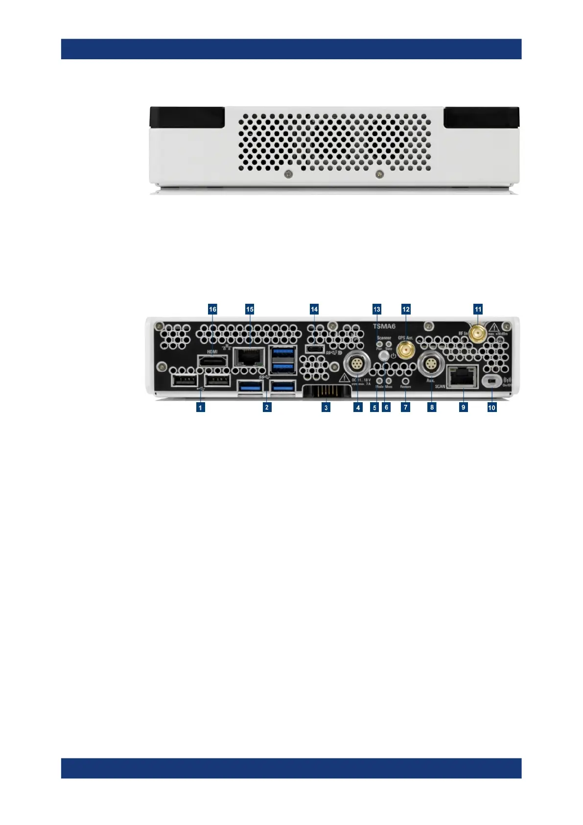
3.2.2 Rear panel view
The following figure provides an overview of the control elements and the connectors
on the rear panel of the instrument.
Figure 3-7: R&S TSMA6 - Rear Panel
1 = "USB 2.0 (2x, Type A)" on page 31)
2 = "USB 3.0 (4x, Type A)" on page 32
3 = "Docking connector" on page 32
4 = "DC IN connector" on page 32
5 = Status LEDs - Mode, Meas
6 = "Power on/off" on page 32
7 = "Restore button" on page 32
8 = "AUX connector (SMA) - synchronization R&S TSME4/6 / R&S TSMExxDC" on page 32
9 = "SCAN port - GBit LAN interface - external R&S TSME4/6 (RJ45 connector)" on page 33
10 = "WLAN/Bluetooth on/off" on page 33
11 = "RF IN connector (SMA)" on page 33
12 = "GPS Ant. connector (SMA) - GPS antenna input" on page 33
13 = Status LEDs Pwr / State
14 = "USB-C (multiport for Thunderbolt, display and standard USB-C 3.1)" on page 33
15 = "LAN Port - remote control (RJ45 connector)" on page 33
16 = "HDMI connector" on page 34
USB 2.0 (2x, Type A)
See (1) in Figure 3-7.
Connecting external devices, e.g. keyboard, mouse or software dongle.
Power limit: max. 500 mA / port
Overall USB current (USB-C, USB 3.0 and USB 2.0): max. 3 A
Instrument tour