Rexroth IndraDrive Appendix 19-1
DOK-INDRV*-SYSTEM*****-PR02-EN-P
19 Appendix
19.1 Technical Data "Capacitances Against Ground"
The indicated capacitance values help selecting appropriate mains filters
of the HNF01 and NFD03 lines.
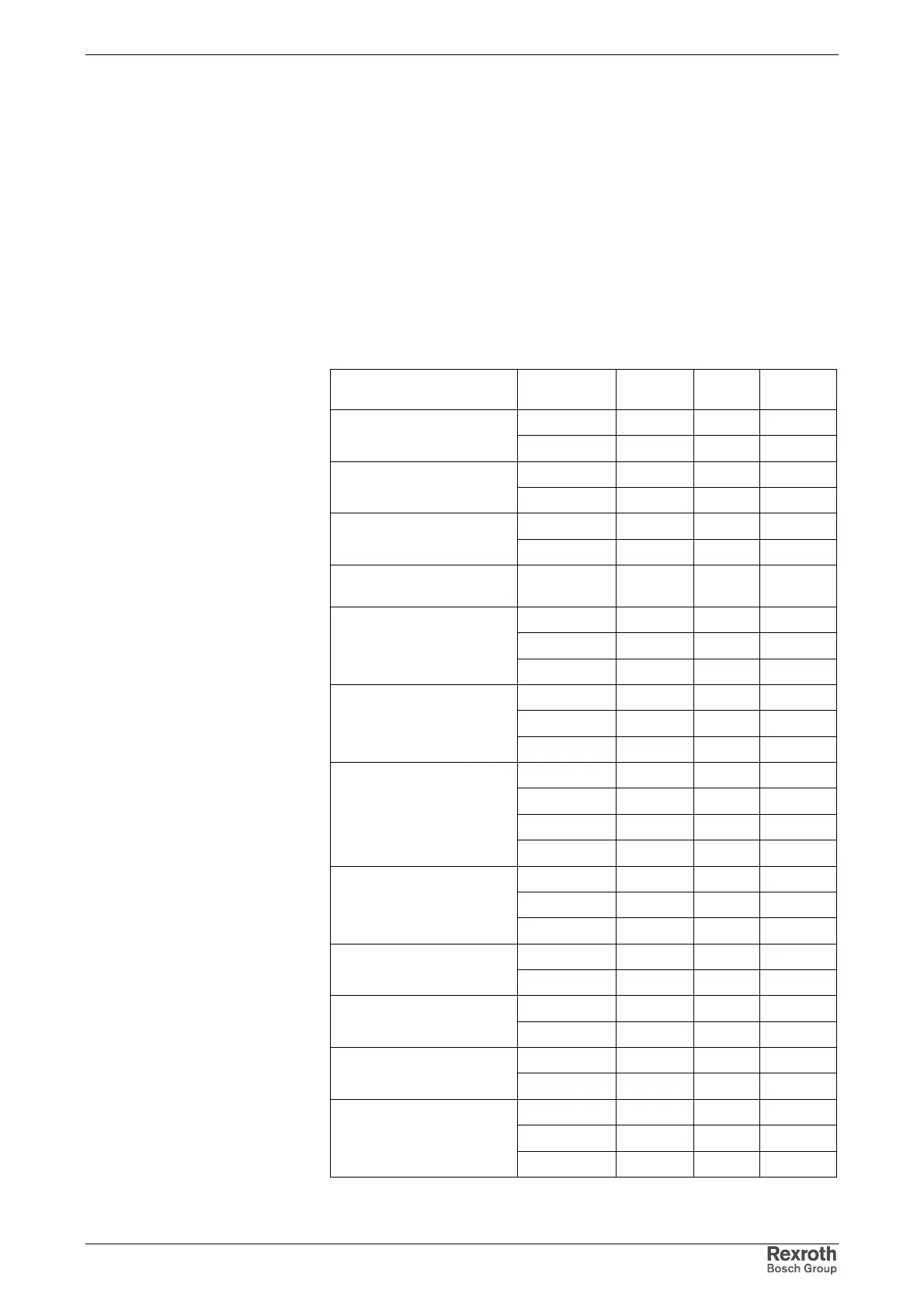
Capacitance Data for Motors
The Rexroth motors have the typical capacitance values listed below. The
data refer to the total capacitance of the power connections U, V, W
against the motor housing.
Motor types Frame length Symbol Unit Typ.
value
AC
_ab
nF
MKD025,
MKE037
BC
_ab
nF 1,0
AC
_ab
nF
MKD, MHD, MHP041,
MKE047
BC
_ab
nF 1,6
AC
_ab
nF 1,2
MKD, MHD, MHP071
BC
_ab
nF 2,5
MKD, MHD, MHP090,
MKE098
BC
_ab
nF 6,7
AC
_ab
nF 4,8
BC
_ab
nF 7,8MHD, MHP093
CC
_ab
nF 9,5
AC
_ab
nF 3,7
BC
_ab
nF 5,3MHD, MHP095
CC
_ab
nF 6,7
AC
_ab
nF 5,3
BC
_ab
nF 10,3
CC
_ab
nF 14,1
MKD, MHD, MHP112,
MKE118
DC
_ab
nF 20,2
AC
_ab
nF 6,9
BC
_ab
nF 13,2MKD, MHD, MHP115
CC
_ab
nF 18,2
BC
_ab
nF 13,9
MHD131
DC
_ab
nF 25,7
BC
_ab
nF 2,1
MSK050
CC
_ab
nF 2,6
BC
_ab
nF 2,1
MSK060
CC
_ab
nF
CC
_ab
nF 3,1
DC
_ab
nFMSK070
EC
_ab
nF
Fig. 19-1: Leakage capacitance of selected motors