7-6 Arranging the Components in the Control Cabinet Rexroth IndraDrive
DOK-INDRV*-SYSTEM*****-PR02-EN-P
Distances on Top and Bottom of Components
Owing to power dissipation in the components, the temperature of the
cooling air current at the device outlet is rising to values higher than
ambient temperature at device inlet.
CAUTION
Property damage due to temperatures higher
than 105°C!
⇒
Comply with indicated minimum distances!
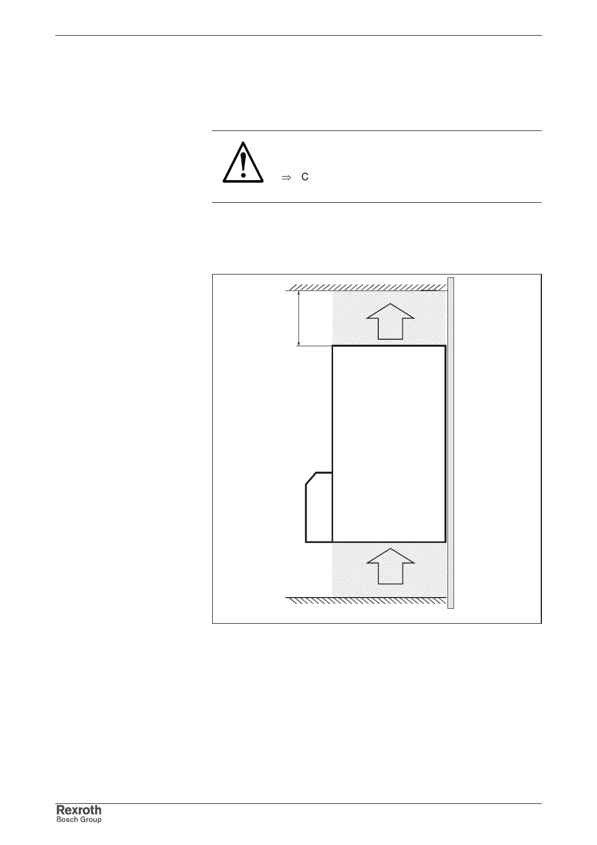
In order that drive controllers can discharge the power dissipation
generated inside of them, they need space on their top (A) and bottom
(B).
kuehlluft.FH7
d
A
B
C
A: air intake
B: air outlet
C: mounting surface in control cabinet
d: distance to top of device
Fig. 7-6: Air intake and air outlet at drive controller
At the components without integrated braking resistor (HMS01, HMD01,
HCS03, HLC01) the minimum distance d for sufficient ventilation is
• 80 mm at the bottom and
• 80 mm at the top
so that the outlet temperature of 105°C is not exceeded at max. ambient
temperature.
Minimum Distance for
Ventilation