Rexroth IndraDrive Arranging the Components in the Control Cabinet 7-7
DOK-INDRV*-SYSTEM*****-PR02-EN-P
The minimum distance for ventilation does not take the additional
dimensions of accessories (e.g. HAS02) into account; for these
dimensions see the dimension sheets.
For components with integrated braking resistor (supply modules, DC bus
resistor units, HCS02 drive controllers) their higher outlet temperatures
have to be taken into account.
To determine the required distances the resulting outlet temperatures are
indicated in diagrams in the technical data of the components.
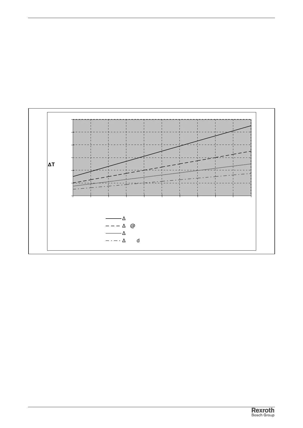
Input value in the diagrams is the generated power of the braking
resistors or the individual output current. See exemplary diagram below:
0
20
40
60
80
100
120
0 50 100 150 200 250 300 350 400 450 500
P
BD
[W]
∆
T [K]
∆
T @ d~0mm
∆
T @ d~40mm
∆
T @ d~80mm
∆
T @ d~120mm
P
BD
: average continuous braking resistor power
d: distance to top of device
Fig. 7-7: Exemplary diagram
The minimum distance for these mounting parts results from the
intersection of the input value with the allowed temperature rise.
If there are different minimum distances for the individual components in
a drive system, the greatest distance determines the minimum distance to
be observed.
The braking resistor in the HMV01.1E heats up during operation, the
braking resistor in the HMV01.1R after power is switched off. For
materials that can be damaged by heat generation, such as lines or cable
ducts, a minimum distance of 300 mm to the top and 40 mm to the side
has to be observed.
Minimum Distance to Mounting
Parts
Minimum Distance to Braking
Resistor
Minimum Distance at HMV01.1
Devices