7-10 Arranging the Components in the Control Cabinet Rexroth IndraDrive
DOK-INDRV*-SYSTEM*****-PR02-EN-P
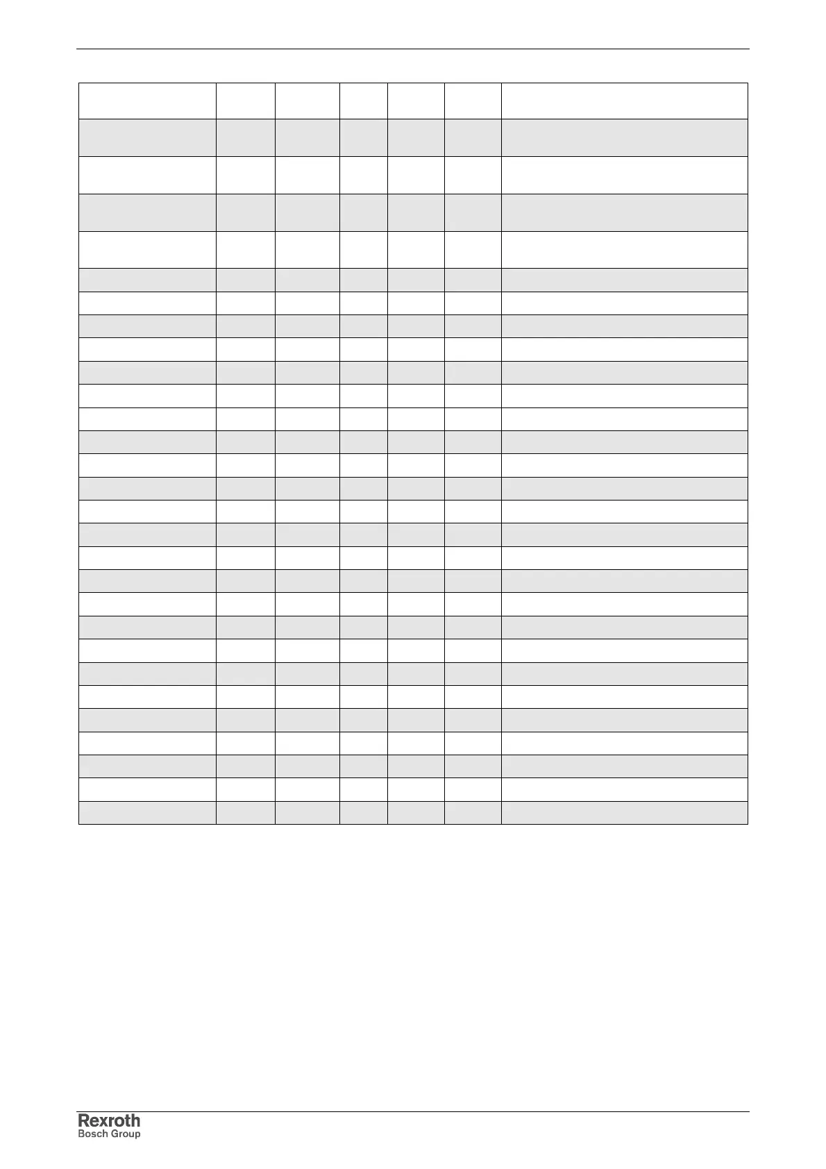
Device
K
[mm]
L
[mm]
M
[mm]
P
[mm]
R
[mm]
Notes
HCS02.1E-W0012 0 316 32,5 13 7
observe additional distance to lateral
neighboring devices
HCS02.1E-W0028 0 378 32,5 13 7
observe additional distance to lateral
neighboring devices
HCS02.1E-W0054 55 378 25 13 7
observe additional distance to lateral
neighboring devices
HCS02.1E-W0070 55 378 25 13 7
observe additional distance to lateral
neighboring devices
HCS03.1E-W0070 75 466 25 13 7
HCS03.1E-W0100 175 466 25 13 7
HCS03.1E-W0150 175 466 25 13 7
HCS03.1E-W0210 250 466 25 13 7
HMV01.1E-W0030 100 466 25 13 7
HMV01.1E-W0075 200 466 25 13 7
HMV01.1E-W0120 300 466 25 13 7
HMV01.1R-W0018 125 466 25 13 7
HMV01.1R-W0045 200 466 25 13 7
HMV01.1R-W0065 300 466 25 13 7
HMS01.1N-W0020 0 466 25 13 7
HMS01.1N-W0036 0 466 25 13 7
HMS01.1N-W0054 0 466 25 13 7
HMS01.1N-W0070 50 466 25 13 7
HMS01.1N-W0150 100 466 25 13 7
HMS01.1N-W0210 150 466 25 13 7
HMD01.1N-W0012 0 466 25 13 7
HMD01.1N-W0020 0 466 25 13 7
HMD01.1N-W0036 0 466 25 13 7
HLB01.1C 0 378 32,5 13 7
HLB01.1D 50 466 25 13 7
HLC01.1C-01M0 0 378 25 13 7
HLC01.1C-02M4 0 378 25 13 7
HLC01.1D-05M0 0 466 25 13 7
Fig. 7-10: Boring dimensions
Ground the housings of the drive controllers!
1. Connect the bare metal back panel of the drive controller in
conductive form to the mounting surface in the control cabinet.
2. Use the supplied mounting screws and fix the screws with a
tightening torque of typ. 6 Nm.
3. Connect the mounting surface of the control cabinet in conductive
form to the equipment grounding system.