Rexroth IndraDrive Arranging the Components in the Control Cabinet 7-11
DOK-INDRV*-SYSTEM*****-PR02-EN-P
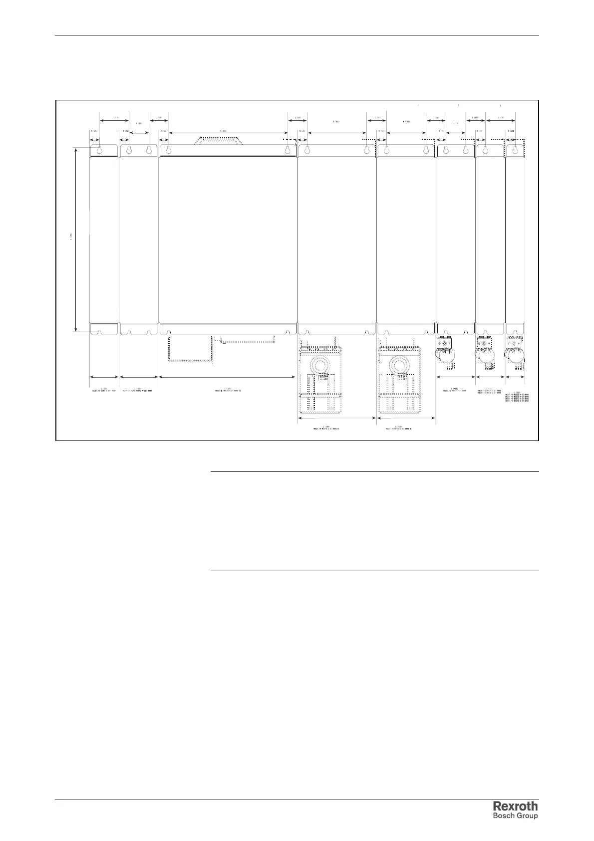
Combination of Drive Controllers of the
Rexroth IndraDrive M Product Range
C
C
C
CC
C
CC
L
K
K
K
K
K
M
M
M
M
Z
Z
M
M
M
M
ZZZ ZZ
HLC01.1D-05M0
HLB01.1D-02K0
HMV01.1E-W0120
HMS01.1N-W0210
HMS01.1N-W0150
HMS01.1N-W0070
HMS01.1N-W0054
HMD01.1N-W0036
HMS01.1N-W0036
HMS01.1N-W0020
HMD01.1N-W0020
HMD01.1N-W0012
DM000005v01_nn.fh
Fig. 7-11: Rexroth IndraDrive M components
Note: The prevailing grid of fixing bores within the
Rexroth IndraDrive M product range is 25 mm.
For performance-dependent arrangement of the components
see Rexroth IndraDrive M Fig. 7-20: Example of an
arrangement.
The HAS02 accessories in the figure require additional
mounting clearance.