BRP-Rotax
REPAIR MANUAL
INSTALLATION OF COMBUSTION CHAMBER INSERT
General
NNOOTTEE
Note the installation position of the combustion chamber insert (2) - “Made in Aus-
tria” points to the exhaust port.
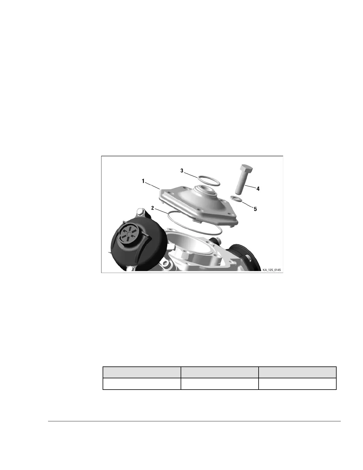
Instructions See Figure: Combustion chamber insert.
Proceed as follows to install the combustion chamber insert and cylinder head cover:
1. Position O-ring (2) in the groove of the cylinder.
2. Tighten combustion chamber insert (2) crosswise with 5 hex screws (4) and with lock wash-
ers (5) to 5 Nm initially, ensuring that the O-ring (3) is not crushed. Tighten to tightening tor-
que 30 Nm (22 ft.lb).
Figure 4.27: Combustion chamber insert
1 Combustion chamber insert 2
O-ring 64x2
3
O-ring 23.3x2.4
4 Hex. screw M8x30
5 Lock washer
______________________________________________________
INSTALLATION OF CYLINDER HEAD COVER
Special tools The following special tools and equipment are required:
Part no. Description
Field of application
897651
LOCTITE 243 Screw locking
Preparation The following preparation is required before installation:
• Installation of the coolant thermostat:
Effectivity: 125 MAX evo, Junior MAX
evo, Mini MAX evo, Micro MAX evo
Edition - February 01 2018 /Rev. 0
Chapter 4
Page 29

 Loading...


