Sirius 800 Series User Manual Nucleus 2450 Router Controller Card Nucleus Router Control Modules 14.5
Iss 5 Rev 7 Page 272 © 2017 SAM
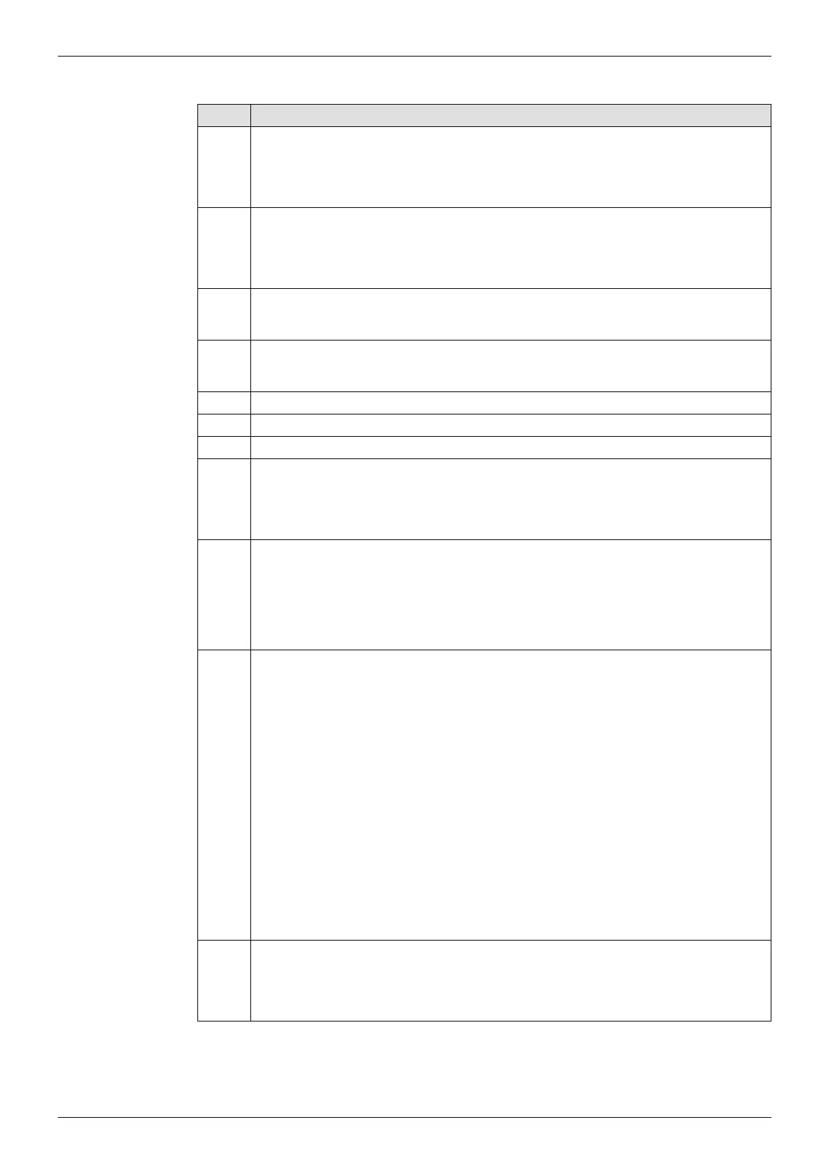
Table 73 lists the 2450 Nucleus router control module LEDs.
LED Description
D4
Active/Idle
•Blue = Active
• Purple (Blue + Red) = Idle
D5
100Mb Ethernet
• Green = 100 Mb (Ethernet)
• Off = 10Mb Ethernet
D6
Ethernet Link
• Flashes = Ethernet activity
D9
Crosspoint Switch
• Toggles between Blue and Off each time a Crosspoint is switched
D10 Not used
D11 Not used
D12 Not used
D13
Communications to other processor
• Green = Communications to other processor
• Off = No communications to other processor
D14
LTC
• Flashes Blue = 625 TC present
• Green = 525 TC present,
• Off = TC not present
D15
When the Nucleus Controller powers up, if it detects a difference between what was
configured last and the current configuration, it applies the new configuration and
the D15 LED shows an FPGA validation error, see Figure 182 The next time the
Nucleus Controller is rebooted there is no mismatch and therefore the D15 LED is
off. If the D15 LED remains on, it could indicate a fault in the interface to the
modules.
An FPGA interface validation error occurs if the software detects a difference
between the modules configured in the database and the configuration last written
to the modules in the frame. This can happen when a reconfigure is done to
recognise new cards and the Nucleus Controller is rebooted.
On a dual processor system, the D15 LED can indicate a mismatch between the
databases on the two controllers.
• Red = FPGA interface validation error
•Off = no error
D16
Active/Idle
• Flashes Green = Active
• Flashes Red = Idle
Table 73 2450 Nucleus Router Control Module LEDs