Installing and connecting the device
3.1 Preparing for installation
ITC V3, ITC V3 PRO
44 Operating Instructions, 03/2024, A5E42761061-AF
3.1.3.3 Preparing the mounting cutout
Stability of the mounting cutout
The material in the area of the mounting cutout must provide sufficient strength to
guarantee the enduring and safe mounting of the HMI device.
The force of the mounting clips or operation of the device may not lead to deformation of the
material in order to achieve the degrees of protection described below.
Degrees of protection and installation area
The degrees of protection of the HMI device can only be guaranteed if the following
requirements are met:
• Material thickness at the mounting cutout for degree of protection IP65 or Type 4X/12
(indoor use only, front face only): 2 mm to 6 mm
• Permitted deviation from plane at the mounting cutout: ≤ 0.5 mm
This condition must also be fulfilled for the mounted HMI device.
• Permitted surface roughness in the area of the mounting gasket: ≤ 120 µm (Rz 120)
• The installation area is dry and free from contamination such as dust or lubricant.
Compatibility of the mounting cutout to other HMI devices
The Industrial Thin Client built-in units are compatible with SIMATIC Industrial PCs, Industrial
Flat Panels, HMI devices and SINUMERIK TOP Panels of the same series with corresponding
display size.
Note that despite the same dimensions for the mounting cut-out, the device depth of ITC V3
devices can differ from the device depth of the compatible devices.
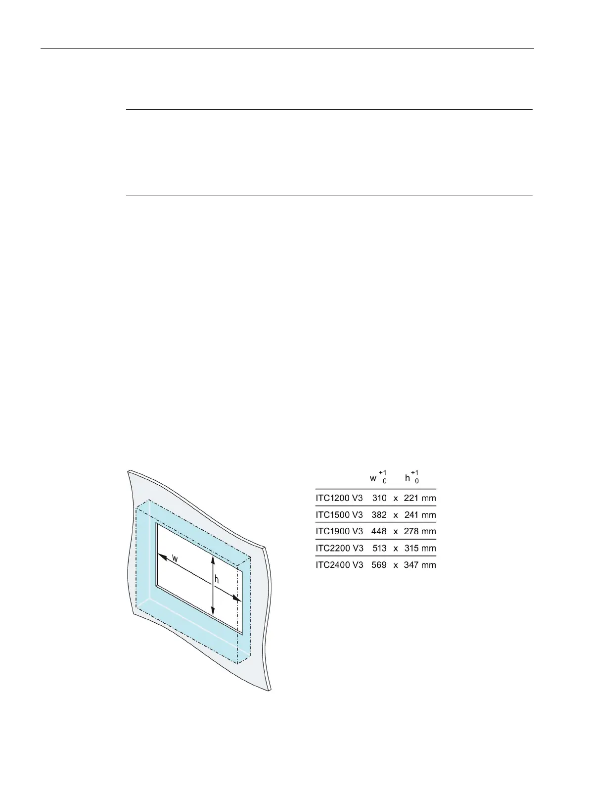
Dimensions of the mounting cutout
The width and height values must be reversed accordingly for mounting in portrait format.