Technical specifications
8.2 Electromagnetic compatibility
ITC V3, ITC V3 PRO
Operating Instructions, 03/2024, A5E42761061-AF
173
8.2 Electromagnetic compatibility
The HMI device satisfies, among other things, the requirements of the EMC guidelines of the
European domestic market.
EMC-compatible installation of the HMI device
The EMC-compliant installation of the HMI device and the application of interference-proof
cable is the basis for interference-free operation.
Observed the following manuals in addition to these operating instructions:
• Designing interference-free controllers
(https://support.industry.siemens.com/cs/ww/en/view/59193566)
• Industrial Ethernet/PROFINET – Passive network components
(https://support.industry.siemens.com/cs/ww/en/view/84922825)
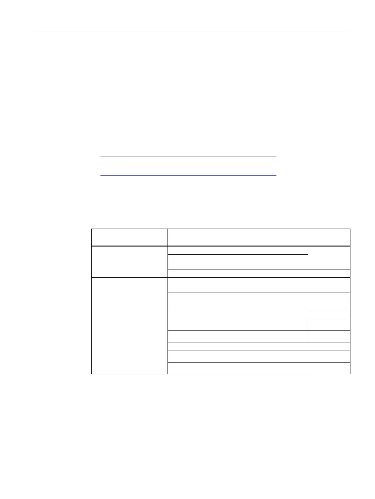
Pulse-shaped disturbance
The following table shows the electromagnetic compatibility of modules with regard to pulse-
shaped interference. The precondition for electromagnetic compatibility is that the HMI
device meets the specifications and guidelines for electrical installation.
Pulse-shaped interference
Corresponds
to Test level
in accordance with
IEC 61000-4-2
Contact discharge: 6 kV (built-in units on the front,
PRO devices all-around)
Contact discharge: 4 kV (built-in units on the rear side)
Bursts
(high-speed transient
disturbance variable)
in accordance with
2 kV supply line
3
(surge) according to
IEC 61000-4-5
Coupling procedure:
42 Ω, 0.5 μF
1
Asymmetric coupling (line to ground):
• 1 kV supply line, direct voltage
2
• 2 kV signal cable/data cable, > 30 m
Symmetrical coupling (line to line):
• 0.5 kV supply line, direct voltage
• 1 kV signal line, > 30 m
3
1
Basically, you must connect the HMI device to your own distribution system (or batteries) via an
upstream local power supply. If you connect the HMI device directly to your own distribution
system, you must provide additional protective measures against overvoltage.