Installing and connecting the device
3.3 Installing a PRO device
ITC V3, ITC V3 PRO
Operating Instructions, 03/2024, A5E42761061-AF
55
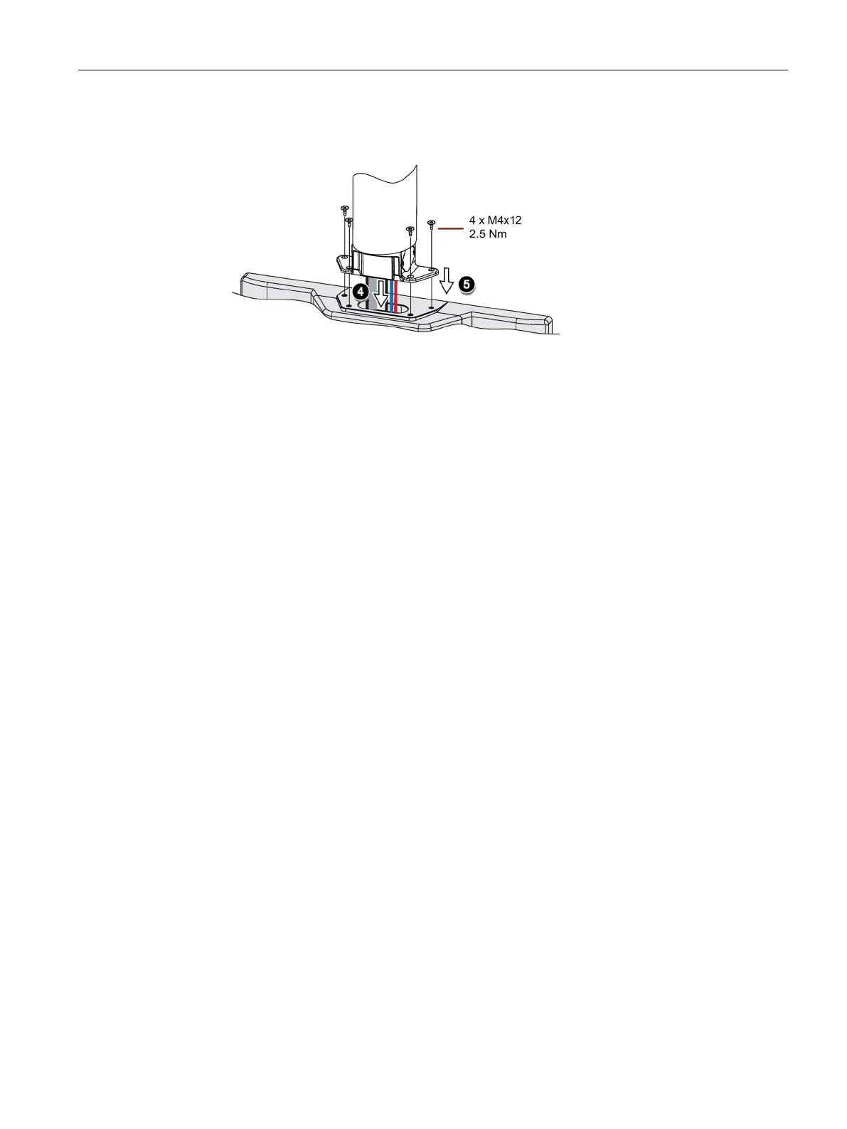
4. Insert all connection cables through the opening of the PRO device. Make sure that the
connection cables are not damaged.
5. Attach the device with 4 M4x12 screws to the base adapter from the top, torque 2.5 Nm.
Make sure that the connection cables are not crushed.
6. Connect all cables according to the description in the section below.
7. Fasten the terminal compartment cover to the device with the 2 screws, torque 1.5 Nm.
Check that the seal is sitting correctly.
3.3.3 PRO devices for support arm (extendable, round tube)
Requirement
• One of the following support arm systems:
– Support arm with round tube end with outside diameter 48.3 mm, appropriate for the
opening of the PRO device
When selecting the round tube, ensure that its inside diameter is large enough so that
all needed cables and their connectors can fit through.
– Support arm with mechanical interface, suitable for the flange of the flange mount
adapter, and Siemens flange mount adapter (not included in product package)
– Support arm with mechanical VESA interface, the corresponding Siemens adapter set
and the Siemens flange mount adapter (not included in product package)
See also section "System components for PRO devices (Page 25)".
• The PRO device, all packaging components and protective films have been removed
• The lower cover of the PRO device from the accessory kit
• The following cables are fed through the support arm to which the device is mounted:
– Cables for the power supply
– Equipotential bonding cable
– Data cables, e.g. PROFINET/Ethernet or USB cable
Procedure
The following figures show an example of how to attach the PRO device to a support arm
system using the optionally available Siemens flange mount adapter. The same approach is
used to mount the PRO device to a 48.3 mm round tube.