Installing and connecting the device
3.4 Connecting the device
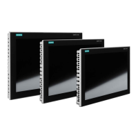
ITC V3, ITC V3 PRO
Operating Instructions, 03/2024, A5E42761061-AF
59
Connection sequence
Damage to the HMI device
If you do not keep to the connection sequence you could damage the HMI device.
Be sure to connect the HMI device in the following sequence.
1. Equipotential bonding
2. Power supply
3. PROFINET/Ethernet
4. USB devices
Disconnect the HMI device by completing the above steps in reverse order.
Connecting the cables
Adhere to the local installation regulations
When connecting the cables, observe the local regulations and the local installation
conditions, such as protective circuits for power supply lines.
Temperature resistance and insulation of the cables
Use cables with a maximum permissible operating temperature that is at least 20 °C more
than the maximum ambient temperature.
The insulation of the cables must be suitable for the operating voltage.
Short-circuit and overload protection
Various measures as protection against short-circuits and overloads are required for setting
up a full installation. The types of components and the degree to which the protective
measures are mandatory depend on the regulation that applies to your system setup.
• When connecting the cables, make sure that you do not bend the contact pins.
• Secure the cable connectors by fastening the connector to the socket with screws.
• Provide adequate strain relief for all cables.
• The pin assignment of the interfaces is described in the technical specifications.