Installing and connecting the device
3.4 Connecting the device
ITC V3, ITC V3 PRO
Operating Instructions, 03/2024, A5E42761061-AF
61
Cable routing for the PRO devices
Since the PRO device is mounted on a pedestal or a support arm instead of in a control
cabinet, the connecting cables must be routed through the support arm or pedestal. The
cross
-sections specified for the built-in units are also valid for the PRO devices.
Follow the corresponding connection diagrams in the Quick Install Guide, which is enclosed
with your PRO device.
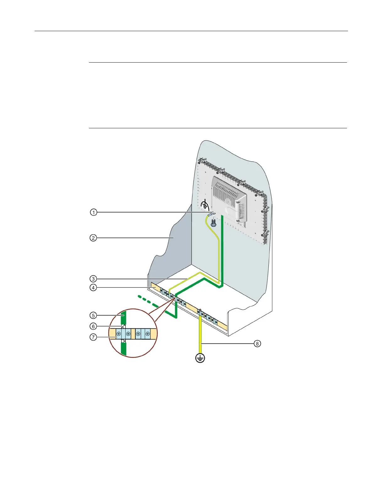
Connection for functional grounding, use a fork cable lug or ring cable lug, size M4
Equipotential bonding cable, 4 mm
2
④ Equipotential busbar for equipotential bonding cables, grounding connection and shield support
Shield of the PROFINET data cable, connected to the equipotential busbar
2