5
05.01
5.8 Control module “SIMODRIVE 611 universal E”
5-139
Siemens AG 2001 All rights reserved
SIMODRIVE 611 Planning Guide (PJU) – 05.01 Edition
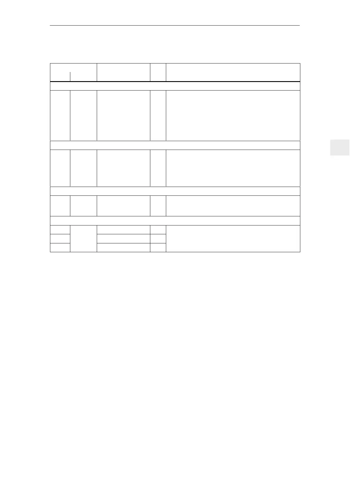
Table 5-19 Overview of the module–specific terminals and interfaces, continued
Terminal Technical dataType
1)
Function
No.
Technical dataType
1)
Function
Desig.
Serial interface (X471)
– X471 Serial interface for
“SimoCom U”
IO Connector type: D–Sub socket, 9–pin
Note:
S The interface can only be used as RS232 interface
S For the cable assignment and pin assignment of the
interface, refer to:
Reference: /FB611U/, Description of Functions
SIMODRIVE 611 universal
PROFIBUS–DP interface (X423) for the optional PROFIBUS–DP3 module
– X423 Communications inter-
face for PROFIBUS
IO Connector type: D–Sub socket, 9–pin
Note:
S Pin assignment, connection diagram and wiring of the
interface:
Reference: /FB611U/, Drive ”SIMODRIVE 611 universal”
Equipment bus (X351)
– X351 Equipment bus IO Ribbon cable: 34–core
Voltages: Various
Signals: Various
Test sockets (X34)
DAU1 Test socket 1
2)
MA Test socket: ∅ 2 mm
DAU2
X34
Test socket 2
2)
MA
Resolution: 8 bits
Voltage range: 0 V to 5 V
M Reference MA
Voltage range: 0 V to 5 V
Max. current: 3 mA
1) I: Input; V: Supply; IO: Input/output; TA: Measuring signal, analog; NC: NC contact; V: supply
2) can be freely parameterized
5 Control Modules

 Loading...


