5
05.01
5.9 Control module ”HLA module”
5-151
Siemens AG 2001 All rights reserved
SIMODRIVE 611 Planning Guide (PJU) – 05.01 Edition
Shut–off valve (axial) supply, 26.5 V external, enable, BERO inputs
S X431: Axis 1
S X432: Axis 2
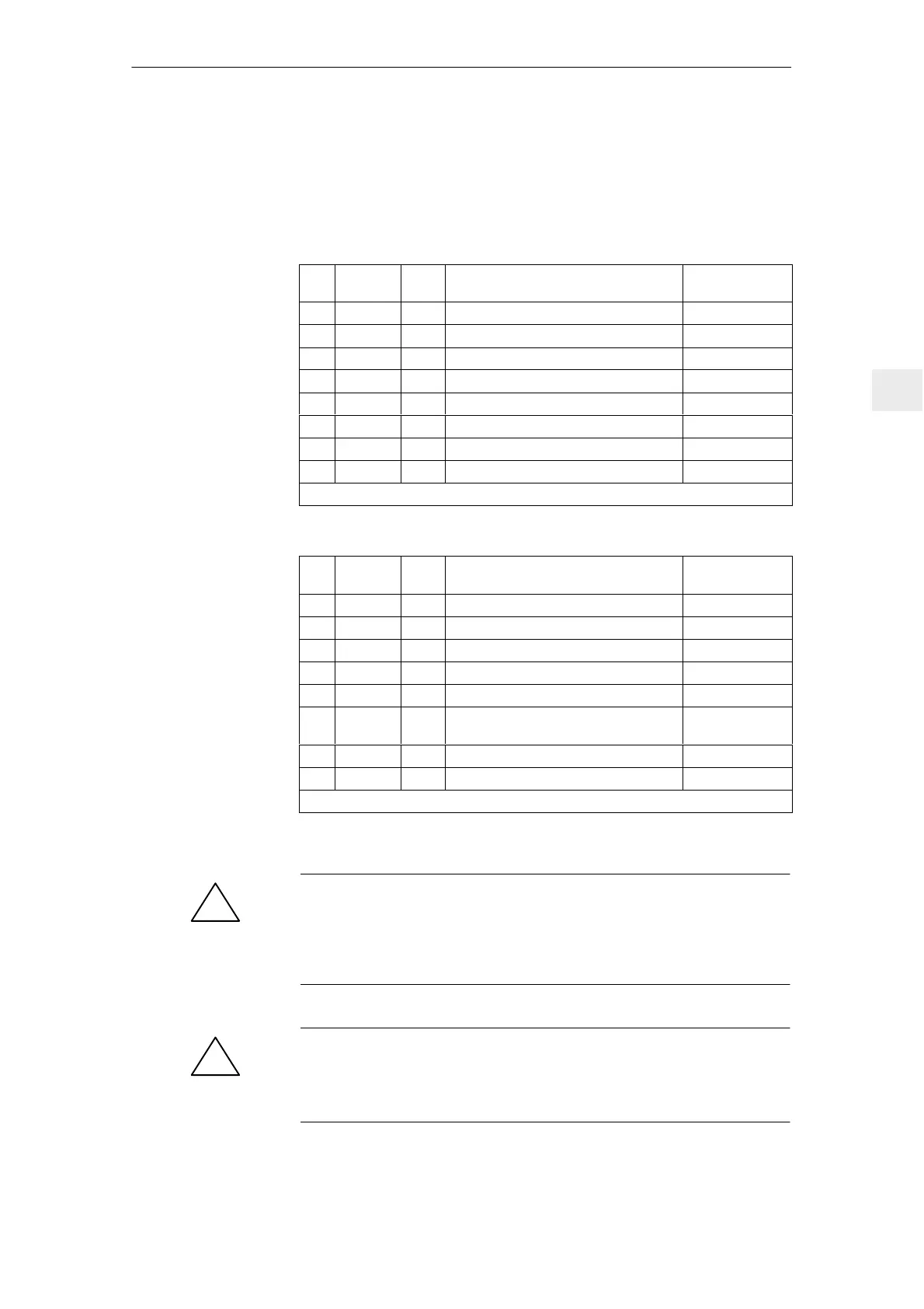
Table 5-25 Connector X431; 8–pin Phoenix Combicon connector
Pin X431 Type
1)
Function Typ. voltage/
limit values
1 M I Electronics ground
2 PV1 O +24V shut–off valve, axis 1 max. 2.0 A
3 MV1 O Ground, shut–off valve, axis 1
4 C1 – Reserved, do not connect
5 P24 I Input +26.5 V external 26.5 V "2 %
6 M24 I Input 0 V external
7 663 I Module–specific enable 21 V...30 V
8 9 O Enable voltage internal +24 V term. 9
1) I = Input, O = Output
Table 5-26 Connectors X432; 8–pin Phoenix Combicon connector
Pin X432 Type
1)
Function Typ. voltage/
limit values
1 M I Electronics ground
2 PV2 O +24V shut–off valve, axis 2 max. 2.0 A
3 MV2 O Ground, shut–off valve, axis 2
4 C2 – Reserved, do not connect
5 B1 I BERO input, axis 1 13 V...30 V
6 19 O Enable voltage internal, ground terminal
19
7 B2 I BERO input axis 2 13 V...30 V
8 9 O Enable voltage internal +24 V terminal 9
1) I = Input, O = Output
Max. terminal cross–section 2.5 mm
2
.
!
Caution
The +24 V outputs, shut–off valve axes 1 and 2 are short–circuit proof. The
energy, absorbed when switching–off inductive loads must be limited by the
user to 1.7 J. When interchanged (incorrect polarity), the outputs are not
protected against overload.
!
Warning
If the 26.5 V supply is connected with the incorrect polarity then the shut–off
valves open immediately, even if the NC or closed–loop control is not operatio-
nal!
Terminals
5 Control Modules

 Loading...


