6
05.01
6.6 DC link options
6-199
Siemens AG 2001 All rights reserved
SIMODRIVE 611 Planning Guide (PJU) – 05.01 Edition
Dimensioning the load duty cycles for pulsed resistors
Desig. Units
Explanation
E Ws Regenerative feedback energy when braking a motor from n
2
to n
1
T s Period of the braking load duty cycle
A s Load duration
J kgm
2
Total moment of inertia (including J motor)
M Nm Braking torque
n RPM Speed
Pn W Continuous rating of the pulsed resistor
P
max
W Peak rating of the pulsed resistor
E
max
Ws Energy of the pulsed resistor for a single braking operation
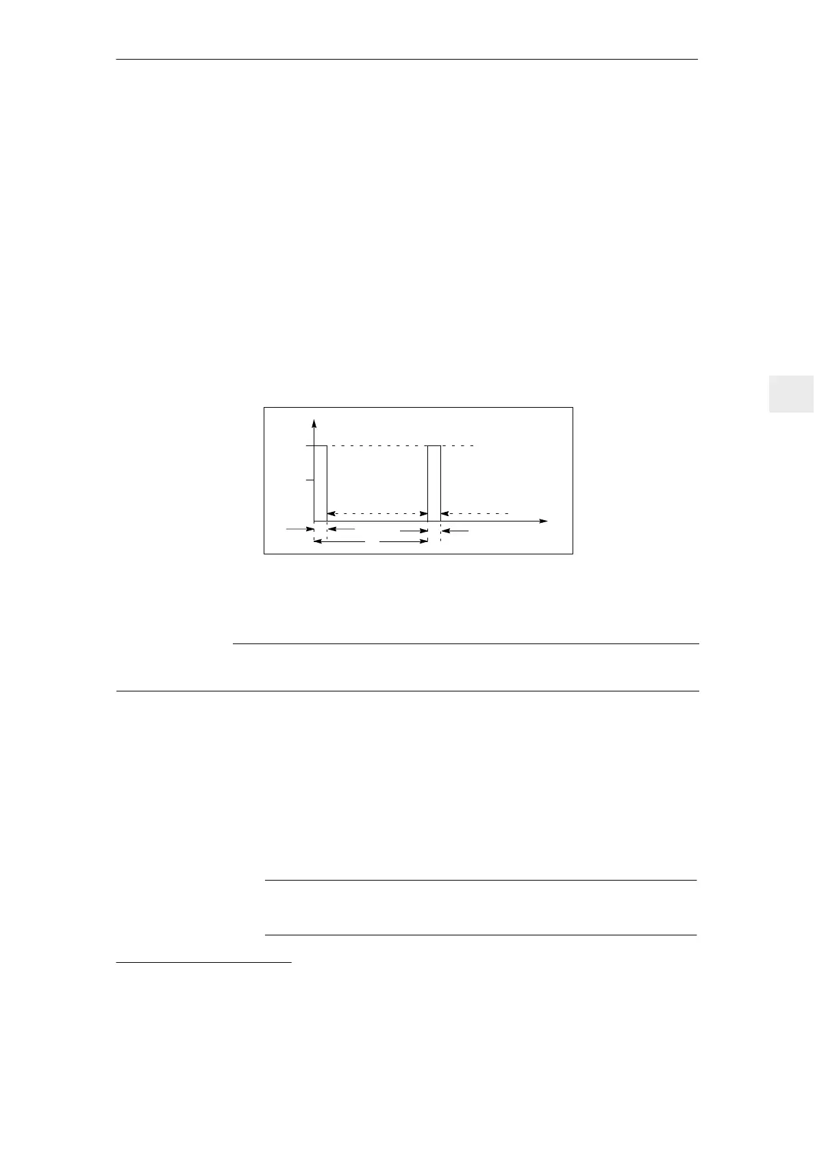
t (s)
P (kW)
P
max
P
n
0 kW 0 kW
A
A
T
Fig. 6-13 Load duty cycle for internal and external pulsed resistors
Table 6-18 Examples
Values Pulsed resistor
0.2/10 kW
Pulsed resistor
0.3/25 kW
Pulsed resistor
1.5/25 kW
E
max
Pn
P
max
13500 Ws
1)
200 W
10000 W
7500 Ws
300 W
25000W
180000 Ws
1500 W
25000W
Example A=
T=
0.2 s
10 s
0.12 s
10 s
0.6 s
10 s
A=
T=
1.35 s
67.5 s
0.3 s
25 s
7.2 s
120 s
All of the following conditions must be fulfilled:
1. P
max
M2πn/60
2. E
max
E; E=J[(2πn
2
/60)
2
–(2πn
1
/60)
2
]/2
3. P
n
E/T
Note
For UI 5 kW and UI 10 kW, it is not possible to connect an external resistor.
1)
As a result of the mechanical dimensions, the resistor can accept a relatively high level of energy.
Engineering
information
applies for
UI 5 kW, 10 kW,
28 kW and
pulsed resistor
module
Load duty cycles
for braking
operations
6 Infeed Modules

 Loading...


