6
05.01
6.6 DC link options
6-200
Siemens AG 2001 All rights reserved
SIMODRIVE 611 Planning Guide (PJU) – 05.01 Edition
Horizontal and vertical mounting positions are possible.
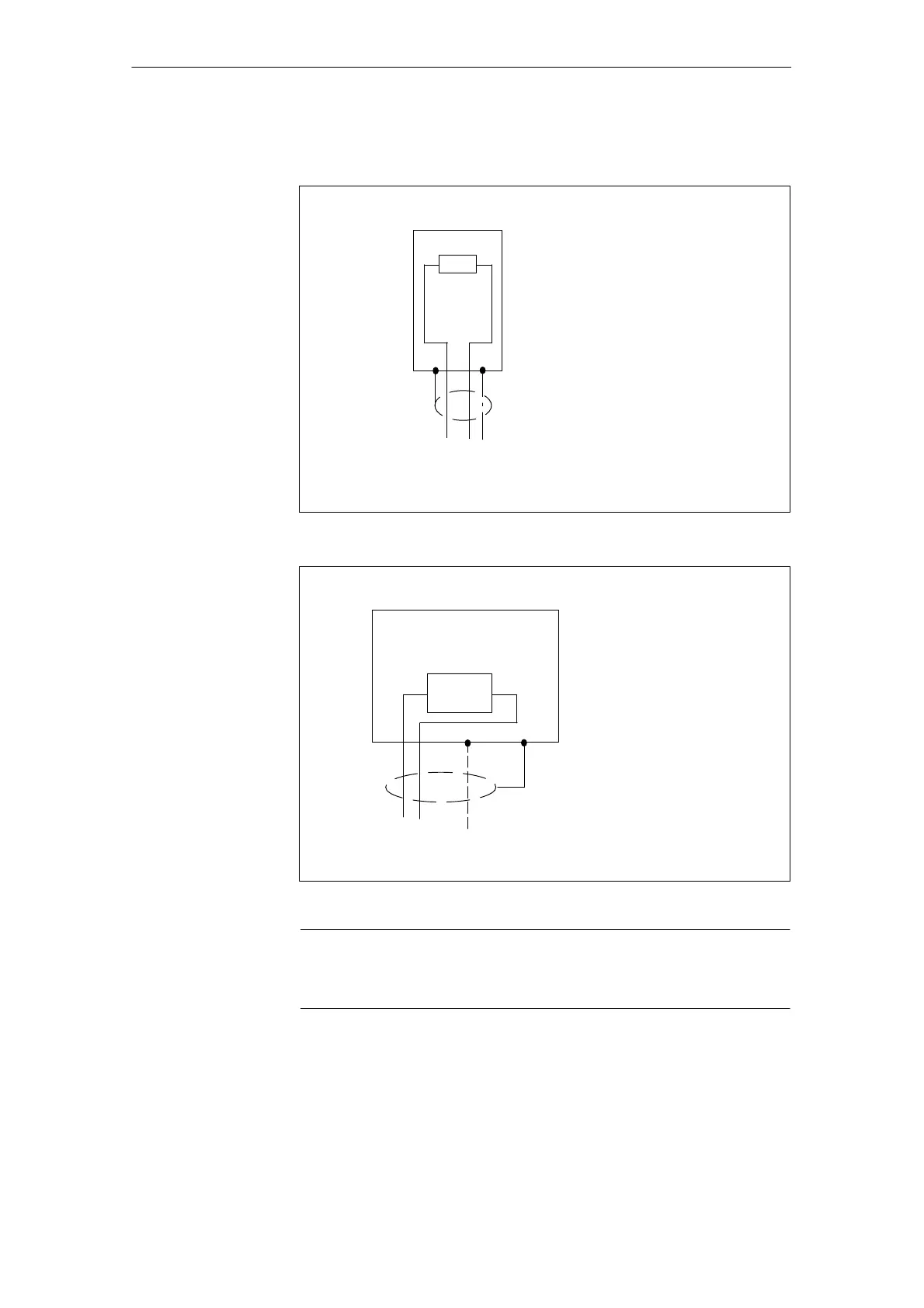
Connection for external pulsed resistor 0.3/25 kW
Order number: 6SN1113–1AA00–0DA0
Red, blue, PE (green, yellow) each 1.5 mm
2
Shielded 3 m connecting cable, can be extended up to 10 m
PE
Fig. 6-14 Connection for external pulsed resistor 0.3/25 kW
Connection for external pulsed resistor 1.5/25 kW
Order number: 6SN1113–1AA00–0CA0
Shield connection is realized through the PG gland
Shielded connecting cable (braided screen) cross–section 2.5 – 4 mm
2
max. length 10 m
PE
1R3R
Fig. 6-15 Connection for external pulsed resistor 1.5/25 kW
Note
Conductors which are not used in multi–conductor cables must always be con-
nected to PE at both ends.
Mounting
positions
6 Infeed Modules

 Loading...


