6
05.01
6.6 DC link options
6-201
Siemens AG 2001 All rights reserved
SIMODRIVE 611 Planning Guide (PJU) – 05.01 Edition
Connection types, pulsed resistor module
Status as supplied:
Connector with jumper between 1R and
2R
Internal resistor active
Order number: 6SN1113–1AB0V–0VAV
P600
M600
Pul-
sed
resi-
stor
mo-
dule
2R
3R
1R
Fig. 6-16 Status of the pulsed resistor module when supplied
Note
For pulsed resistor modules, only the external pulsed resistor 1.5/25 kW can be
connected.
The following connection combinations are possible:
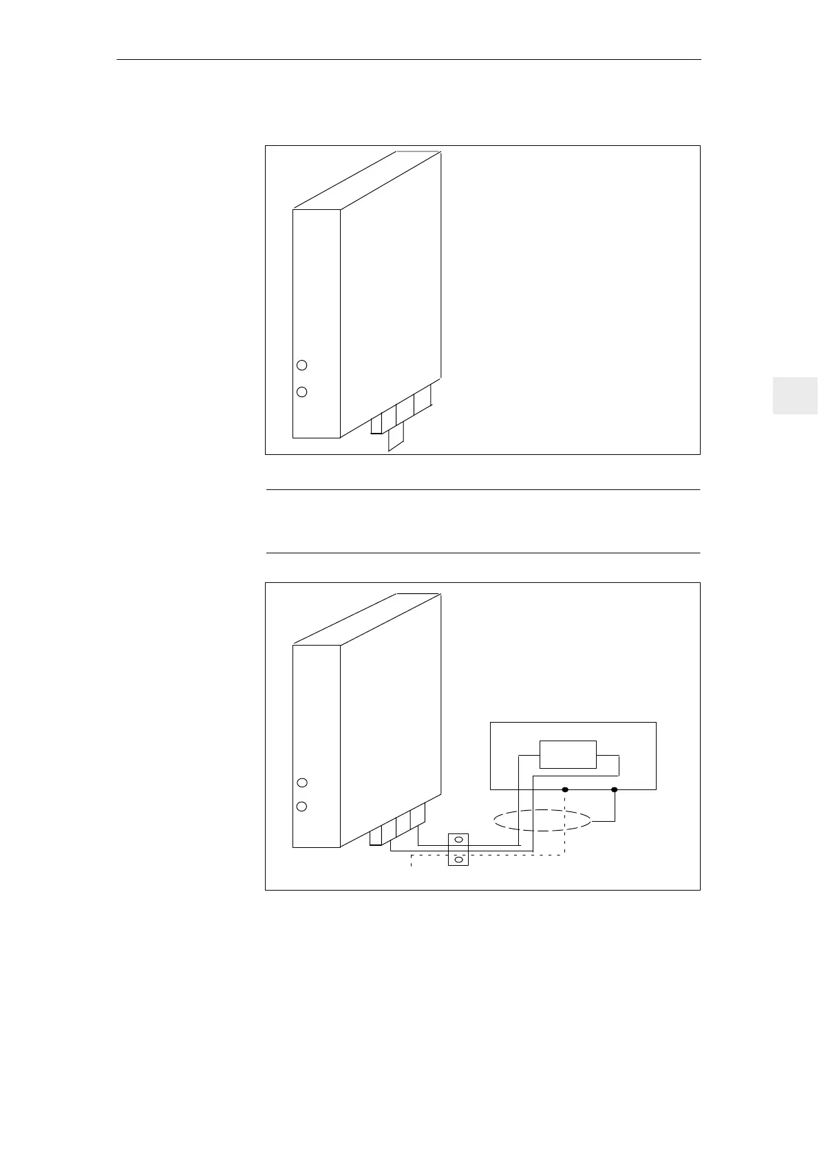
Connection of an external 1.5 kW resistor:
Connector without jumper
Internal resistor is inactive
External resistor is active
1) Shield connection as close as possible to the
module
Order number: 6SN1113–1AB0V–0VAV
P600
M600
Pul-
sed
resi-
stor
mo-
dule
1R
1)
PE
1R
3R
3R
2R
PE rail
Fig. 6-17 Connecting an external 1.5 kW pulsed resistor
Number of pulsed resistor modules connected to the same DC link, refer to
Catalog NC60
NvC / 500 µF
N = max. number of pulsed resistor modules (must always be rounded–off)
C = DC link capacitance of the drive group in µF
Pulsed resistor
module
6 Infeed Modules

 Loading...


