6
05.01
6.6 DC link options
6-202
Siemens AG 2001 All rights reserved
SIMODRIVE 611 Planning Guide (PJU) – 05.01 Edition
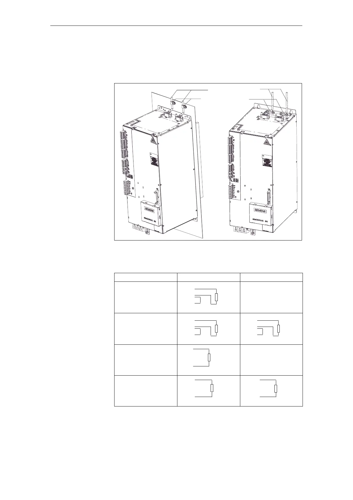
The UI 28 kW module does not include a pulsed resistor.
Ext. pulsed resistor
Screen connection
Fig. 6-18 Connecting an external pulsed resistor with screen connection
Table 6-19 Permissible methods of connecting an external pulsed resistor to UI
28 kW
Pulsed resistor Terminal block TR1 Terminal block TR2
0.3/25 kW
1R
2R
3R
*
Pulsed
resistor
0.3 kW
1R
2R
3R
2 x 0.3/25 kW=0.6/50 kW
1R
2R
3R
*
Pulsed
resistor
0.3 kW
1R
2R
3R
*
PW
0.3
kW
1.5/25 kW
1R
2R
3R
Pulsed
resistor
1.5/25 kW
1R
2R
3R
2 x 1.5/25 kW=3/50 kW
1R
2R
3R
Pulsed
resistor
1.5 kW
1R
2R
3R
Pulsed
resistor
1.5 kW
* Jumper to code the thermal limiting characteristic
J
UI 28 kW module
Possibilities of
connecting exter-
nal pulsed resi-
stors to the 28 kW
module
6 Infeed Modules

 Loading...


