9
05.01
9.1 General information
9-221
Siemens AG 2001 All rights reserved
SIMODRIVE 611 Planning Guide (PJU) – 05.01 Edition
M600
P600
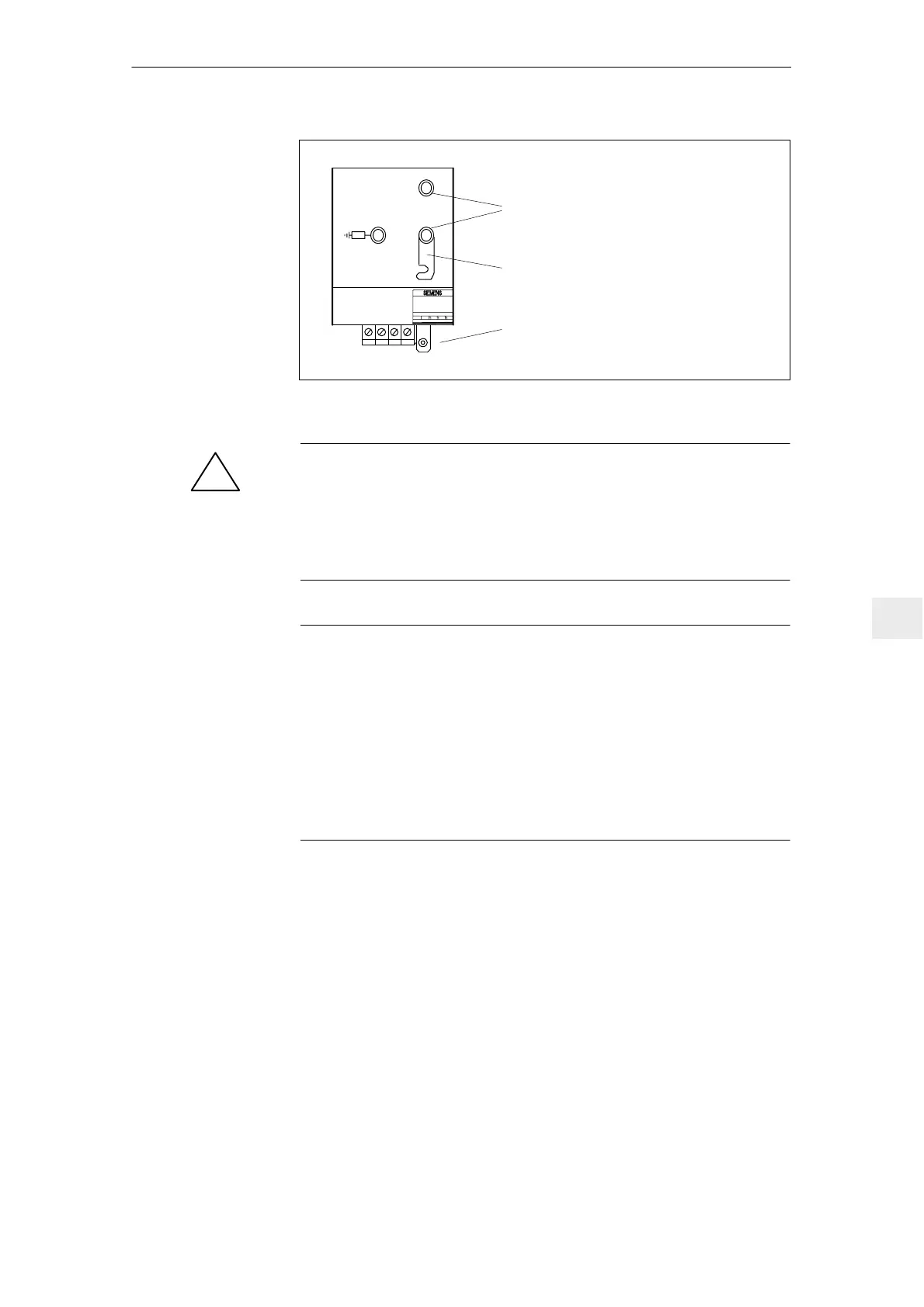
U1 V1 W1 X131 PE
Supply connection
DC link connection
100 kΩ
Grounding bar
Fig. 9-1 NE–module,
!
Warning
The grounding bar is used to ground the M600 DC link bus through resistor
100 kΩ and this should be preferably inserted. When the equipment is
supplied, the grounding bar is open.
If the system is subject to a high voltage test, then the grounding bar must be
opened
Note
The line supply is electrically isolated from the power circuit of the drive group
via the internal line contactor.
The coil circuit can be disconnected to reliably de–energize the line contactor
via the floating contacts, using terminals NS1, NS2 at the NE module. The
DC link will not be pre–charged if the connection is missing when the unit is
powered up.
The connection NS1, NS2 may only be switched when terminal 48 and/or ter-
minal 63 are first de–energized or simultaneously with these terminals, refer to
Section 9.7.
9 Important Circuit Information

 Loading...


