2 System Configuration
2
05.01
2.8 Line supply connection
2-50
Siemens AG 2001 All rights reserved
SIMODRIVE 611 Planning Guide (PJU) – 05.01 Edition
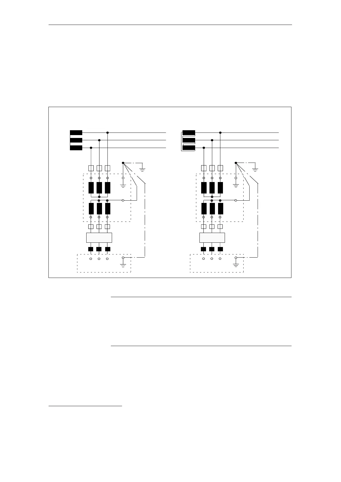
For all other line supply types
1)
the NE module must be connected
through an isolating transformer.
Symmetrical 3–conductor or 4–conductor three–phase line supply without a
directly grounded point, the loads are, e.g. connected to grounding electrodes.
Commutating
reactor
U1 V1 1 W
IT line supply and isolating transformer
Line supply/transformer for the plant
Isolating
transformer
PE
N
L3
L2
L1
NE module
Commutating
reactor
U1 V1 1 W
IT line supply and isolating transformer
Line supply/transformer for the plant
Isolating
transformer
PE
N
L3
L2
L1
NE module
PE
PE
Z Z
Fig. 2-11 Connection diagram, IT line supplies
Note
When using isolating transformers upstream from I/R and UI modules
(module width
100 mm), an overvoltage limiting module should be used,
Order No.: 6SN1111–0AB0V–0AA0; refer to Section 7
UI modules 5 kW Order No.: 6SN1146–2AB00–0BA1, a voltage limiting circuit
is included.
1)
Matching transformer types are described in Catalog NC 60.
IT line supply

 Loading...


