2 System Configuration
2
05.01
2.8 Line supply connection
2-51
Siemens AG 2001 All rights reserved
SIMODRIVE 611 Planning Guide (PJU) – 05.01 Edition
This means, that within the clocked transistor drive converter, the voltage stres-
sing of the insulation distances between the power circuits referred to the line
supply potential and the open–loop and closed–loop control circuits, referred to
the neutral conductor is maintained according to a rated voltage of 300 V in
compliance with DIN EN 50178.
Upstream protective devices to protect against hazardous currents flowing
through the human body or for fire protection (e.g. fault current protective
devices) must be universal devices in compliance with DIN EN 50178. If other
fault current protective devices are used, a transformer with separate windings
must be connected upstream from the drive converter to de–couple it from the
line supply.
DC current components may be present in fault currents which occur due to the
6–pulse three–phase bridge circuit in the line supply infeed module. This should
be taken into account when selecting/dimensioning a fault current protective
device.
The SIMODRIVE unit may be directly connected to TN line supplies with a
universal current–sensitive residual–current protective device with selective
cut–out characteristics as protective measure.
Note
Only I/R modules, 16 kW and 36 kW, may be directly connected to a line
supply with residual–current protective devices.
Delayed universal current–sensitive residual–current protective device with
selective cut–out characteristics can be used without any restrictions to provide
protection against hazardous currents flowing through the human body.
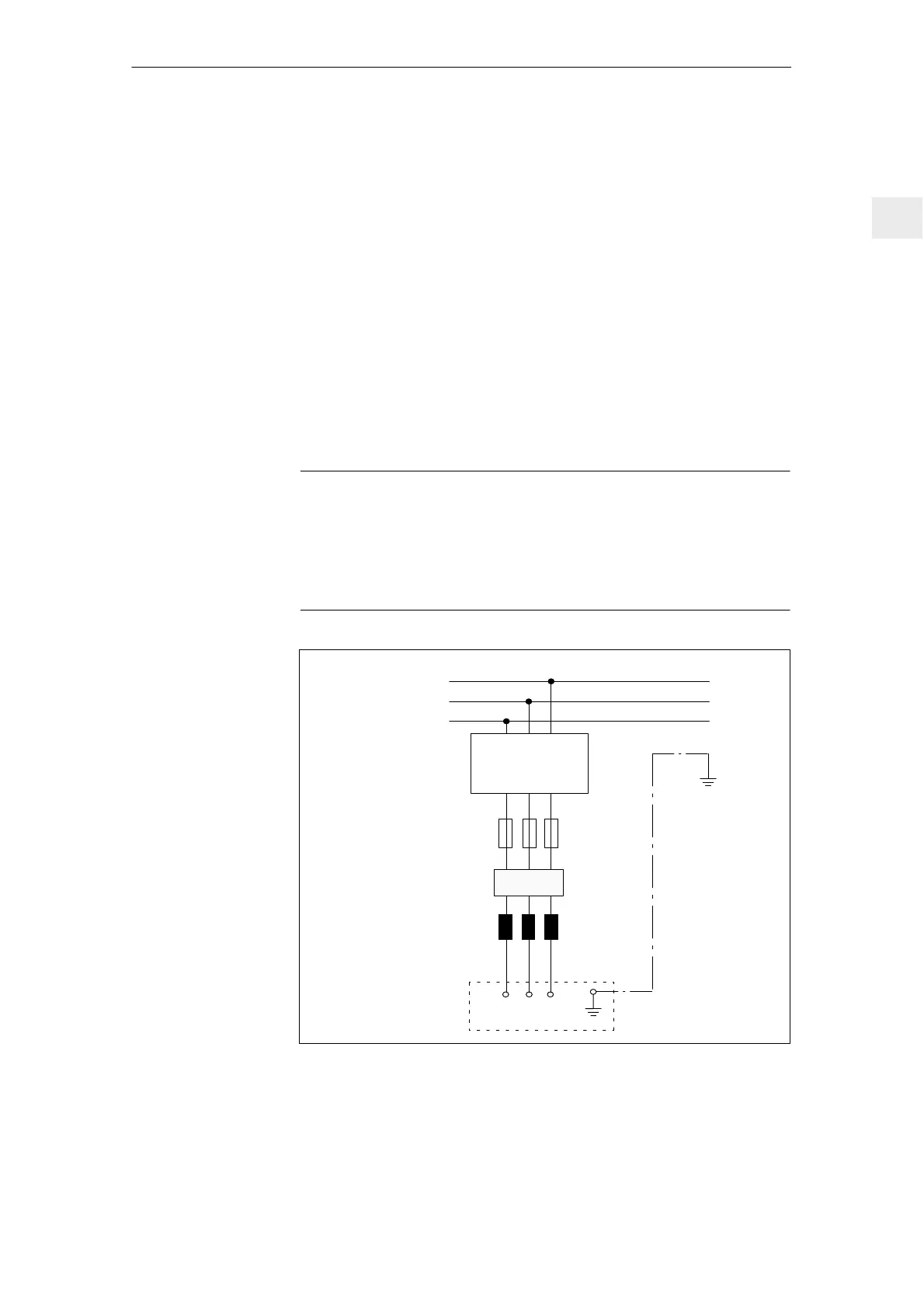
Commutating reactor
U1 V1 1 W
Connection diagram with residual–current protective device
PE
L3
L2
L1
NE module
residual–current
protective device
Universal current–
sensitive
Z
Fig. 2-12 Connection diagram, residual–current protective device
Direct connection
to line supplies
with residual–
current protective
device

 Loading...


