3
05.01
3.4 Direct position sensing
3-57
Siemens AG 2001 All rights reserved
SIMODRIVE 611 Planning Guide (PJU) – 05.01 Edition
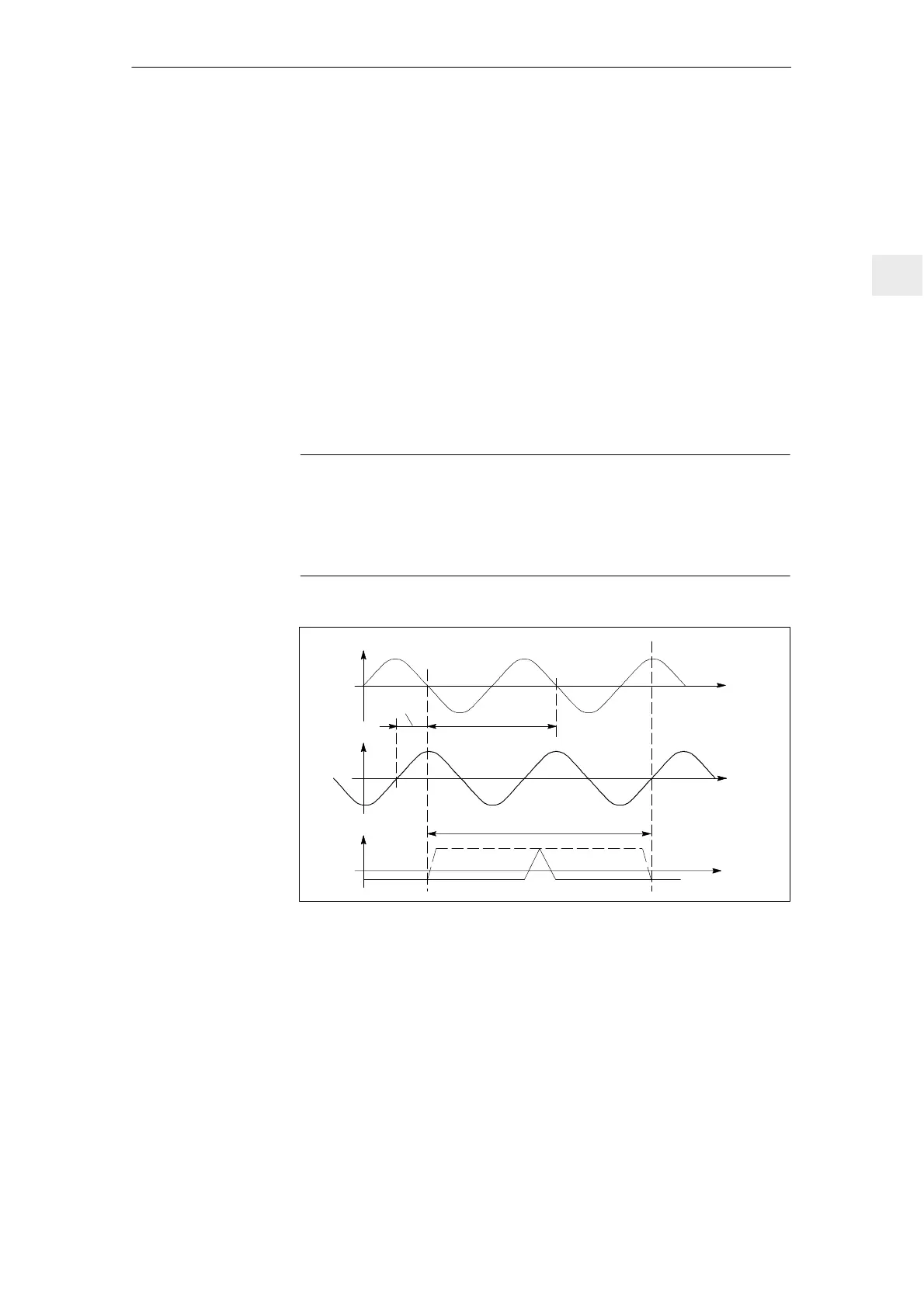
Incremental systems with two sinusoidal current signals A, B, displaced
through 90 degrees and a (for distance–coded systems, several) reference
mark(s) R.
Signal transfer: Differential signals
A, *A; B, *B and R, *R
Amplitude A – *A 7–16 µAss (for R
load
= 1 kΩ)
Amplitude B – *B 7–16 µAss
Amplitude R – *R 2–8 µAss (net component)
Supply: 5 V
5 % (also refer to Section
Encoder power supply)
Max. supply current: 300 mA
Max. encoder signal frequency
which can be evaluated: 200 kHz
Note
For the above mentioned max. encoder signal frequency, the signal amplitude
must be
60 % of the rated amplitude and the deviation of the phase shift
from the ideal 90
d
between tracks A and B x 30
d
.
Observe the frequency characteristics of the encoder signals.
A–*A
B–*B
R–*R
0
0
0
90_el.
360_ el.
Clear signal range
Fig. 3-1 Signal characteristics for a clockwise direction of rotation
3 Motor Selection, Position/Speed Sensing

 Loading...


