3
05.01
3.4 Direct position sensing
3-58
Siemens AG 2001 All rights reserved
SIMODRIVE 611 Planning Guide (PJU) – 05.01 Edition
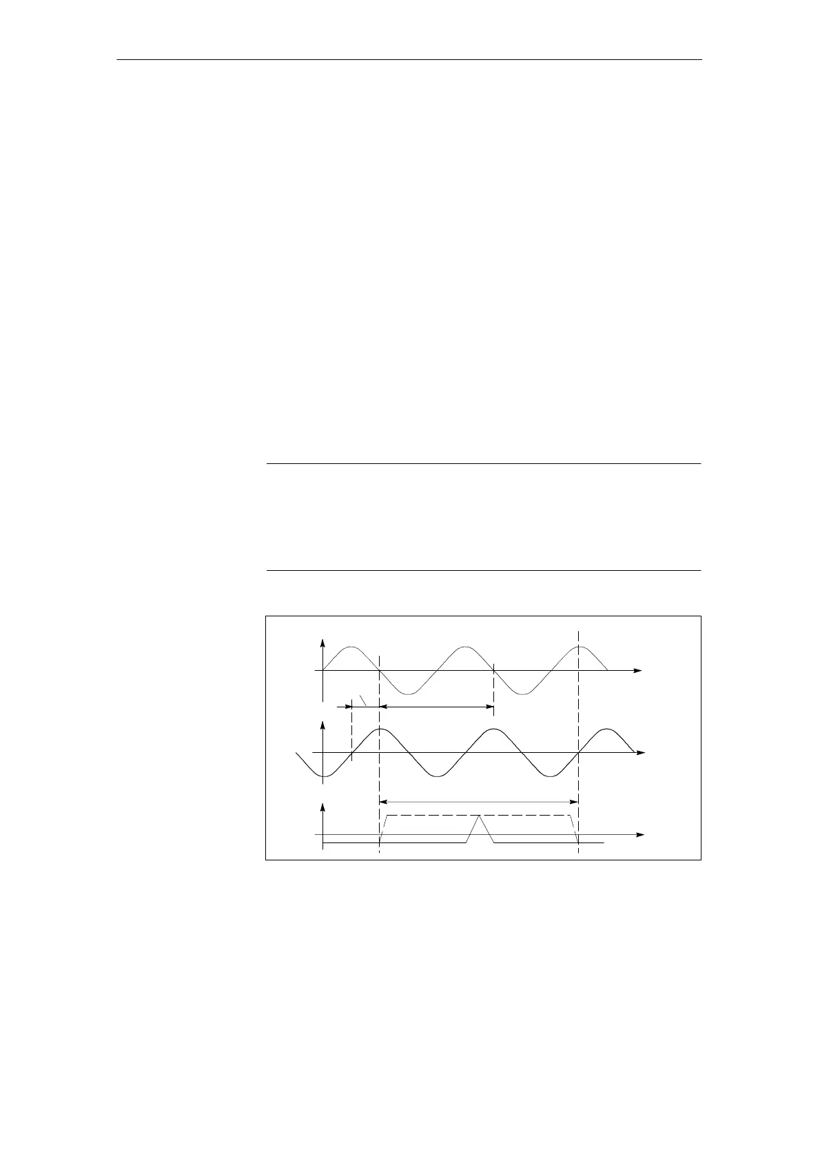
Incremental systems with two sinusoidal voltage signals A, B displaced
by 90 degrees and one (for distance–coded systems, several) reference
mark(s) R.
Signal transfer: Differential signals
A, *A; B, *B and R, R*
Amplitude A – *A 1 Vpp ± 30 %
Amplitude B – *B 1 Vpp ± 30 %
Amplitude R – *R 0.5 Vpp...1 Vpp
Supply: 5 V ± 5 % (also refer to Section
Encoder power supply)
Max. supply current: 300 mA
Max. encoder signal frequency
which can be evaluated: 200 kHz standard module
350 kHz without suppressing the
amplitude monitoring
650 kHz with suppression of the
amplitude monitoring
Note
For the above specified max. encoder signal frequency, the signal amplitude
must be
60 % of the rated amplitude and the deviation of the phase shift
from the ideal 90
d
between tracks A and B 30
d
.
Observe the frequency characteristics of the encoder signals.
A–*A
B–*B
R–*R
0
0
0
90_el.
360_ el.
Clear signal range
Fig. 3-2 Signal characteristics for a clockwise direction of rotation
3 Motor Selection, Position/Speed Sensing

 Loading...


