3
05.01
3.4 Direct position sensing
3-62
Siemens AG 2001 All rights reserved
SIMODRIVE 611 Planning Guide (PJU) – 05.01 Edition
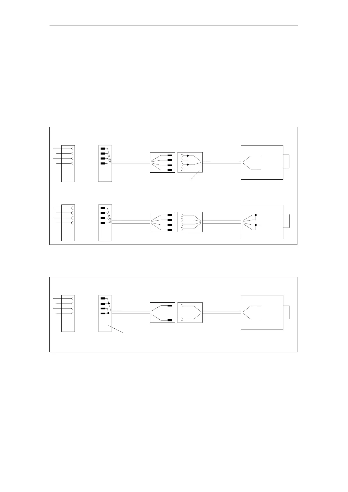
Remote/sense operation
Remote/sense operation
P–encoder
P–sense
M–encoder
M–sense
l ≤ 50 m
l ≤ 5 m
Measuring system without
remote/sense lines
P–encoder
M–encoder
Connections, P–encoder with P–sense and
M–encoder with M–sense must be established
by the customer
Drive module
P–encoder
P–sense
M–encoder
M–sense
l ≤ 50 m
l ≤ 5 m
Measuring system with
remote/sense lines
P–encoder
M–encoder
Drive module
P–sense
M–sense
Fig. 3-5 Signal overview of the connections
Connection system for measuring systems with current signals
P–encoder
P–sense
M–encoder
M–sense
l ≤ 18 m
l ≤ 5 m
Measuring system without
remote/sense lines
P–encoder
M–encoder
Connections, P–encoder with P–sense and M–encoder
with M–sense already exist in SIEMENS cables
Drive module
Fig. 3-6 Signal overview of the connections
No remote/sense operation, max. cable length for 300 mA encoder current
drain, 15 m (for low encoder current drain, appropriately longer cable lengths
are possible, however max. 50 m!).
Main spindle
control with
analog setpoint
interface
Drive control,
Performance
Digital and
standard 2 FD and
MSD
Drive control,
standard Digital
3 Motor Selection, Position/Speed Sensing

 Loading...


